
Mixed valve

A technology of mixing valve and mixing fluid, applied in valve devices, multi-port valves, mechanical equipment, etc., can solve the problem of inability to add hot water flow throttling, etc., and achieve a low-cost and useful structure, easy processing and assembly, and increased leakage. Effect

Active Publication Date: 2011-01-12
FUJIKOKI MFG CO LTD
View PDF2 Cites 0 Cited by
  • Summary
  • Abstract
  • Description
  • Claims
  • Application Information

AI Technical Summary

Problems solved by technology

Therefore, the above conditions (1) and (2) cannot be satisfied at the same time, so it is impossible to add the hot water flow throttling function in addition to the cold water and hot water mixing function

Method used


Image

  • Mixed valve
  • Mixed valve
  • Mixed valve

Examples


Embodiment Construction

[0049] Hereinafter, an embodiment of the mixing valve according to the first embodiment of the present invention will be described with reference to the drawings.

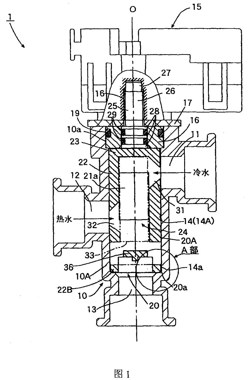
[0050] figure 1 It is a partially cutaway front view showing the first embodiment of the mixing valve of the present invention.

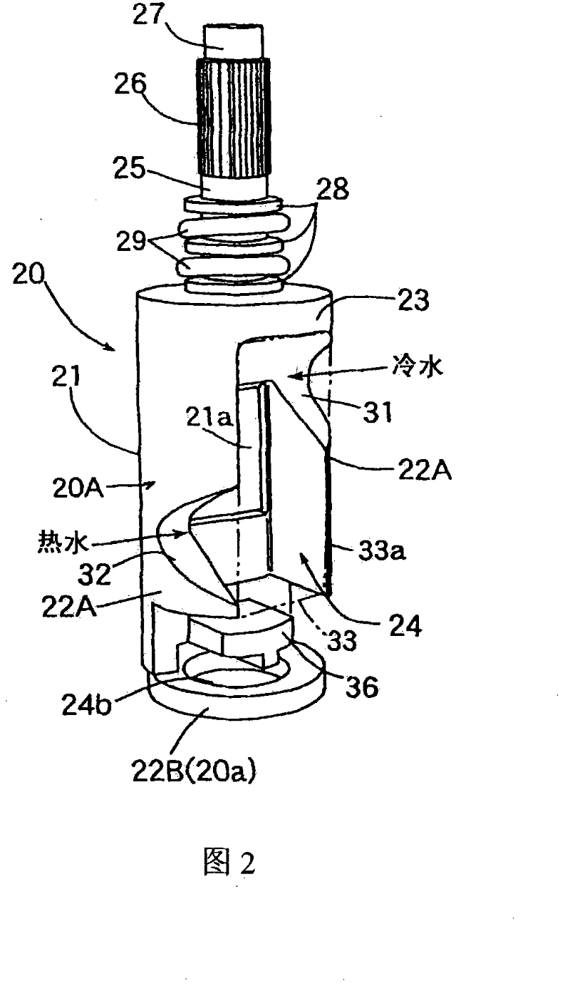
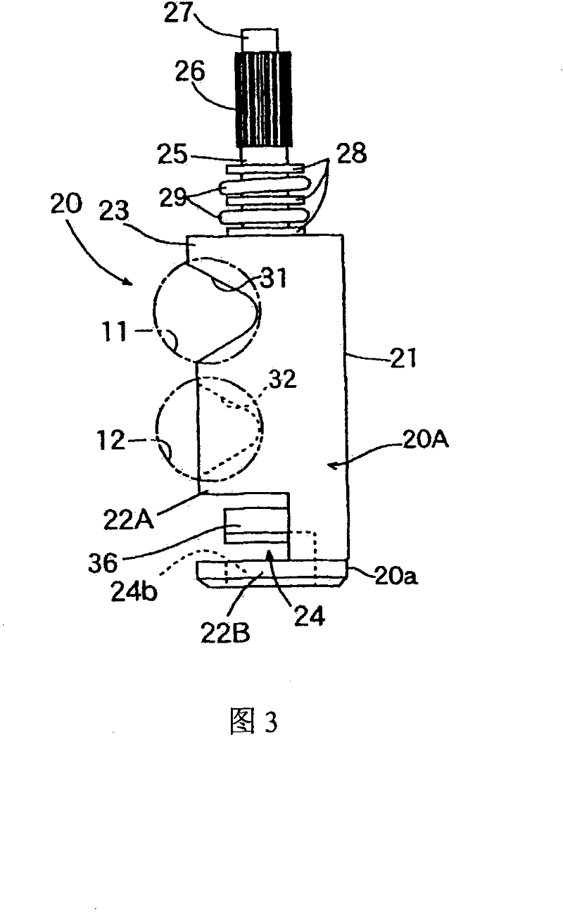
[0051] The mixing valve 1 of the illustrated embodiment is used, for example, in a hot water supply device for mixing cold water and hot water to obtain warm water at a desired temperature. The mixing valve 1 includes: a valve body 10 having a circular cross section. The valve chamber 14 is provided with a cold water inlet 11 connected to the side of the valve chamber 14, a hot water inlet 12, and an outlet 13 connected to the bottom for discharging warm water obtained by mixing cold water and hot water; A rotatable valve core 20 in the valve chamber 14 of the valve body 10; a stepping motor 15 as a driving means for rotating the valve core 20.

[0052] The cold water inlet 11 and the...


PUM


Abstract

A mixed vale comprises a valve body provided with a first guide-in opening, a second guide-in opening and a guide-out opening; and a cylindraceous valve core rotatably embedded in the valve body. The circumferential wall of the valve core is provided with a first opening part and a second opening part corresponding to the first and second guide-in openings, and is provided with a third opening part over the first and second opening parts. When the valve core rotates, the first guide-in opening is made to all close status from all open status, and the second guide-in opening is made to all open status from all close status, when the valve core further rotates and the first guide-in opening is kept at all close status, the third opening part makes the opening area of the second guide-in opening become minimum from maximum continuously. Adopting the invention, a mixed valve with easy assembly and compact structure can be provided which can quickly and correctly obtain the warm water withrequired mixing proportion after mixed the cold water and the hot water, and can regulate the flux of water of one side when the guide-in opening of another side is at all close status.

Description

technical field [0001] The present invention relates to a mixing valve, and particularly relates to a mixing valve suitable for a hot water supply device and the like for mixing cold water and hot water to obtain warm water in a desired mixing ratio. Background technique [0002] As such a mixing valve, for example, Patent Document 1 below discloses a mixing valve having a structure including: a valve body; a rotatable substantially cylindrical valve element inserted into the valve body; The drive means for the rotation of the spool is provided with cold water inlets and hot water inlets at different heights along the rotation axis direction (up and down) of the spool on the valve body, and on the peripheral wall of the spool There are cold water openings and hot water openings of specific shapes for continuously changing the opening areas of the cold water inlet and the hot water inlet, and the mixing ratio of cold water and hot water is adjusted by turning the valve elemen...

Claims


Application Information

Patent Timeline
Patent Type & Authority Patents(China)
IPC IPC(8): F16K11/085
Inventor 梅泽仁志佐藤雅也铃木史宏野村健一
Owner FUJIKOKI MFG CO LTD
Learn More