
Liquid lens optical system and camera lens

A liquid lens and optical system technology, applied in the field of lenses, can solve the problems affecting user experience, insufficient focusing clarity, narrow working distance range, etc., achieve fast auto focus, wide working distance range, and improve production yield. Effect

Active Publication Date: 2022-07-01
深圳术为科技有限公司
View PDF0 Cites 0 Cited by
  • Summary
  • Abstract
  • Description
  • Claims
  • Application Information

AI Technical Summary

Problems solved by technology

[0003] The traditional focusing method mentioned above needs more time to control the lens or lens group to move laterally along the optical axis, so the focusing speed is slow; moreover, in some application scenarios (such as doctors using endoscopes for surgery), due to the need to Manually adjust the knob to focus, which makes the operation inconvenient and affects the user experience
At the same time, some existing zoom lenses still have problems such as narrow working distance range and insufficient focus clarity.

Method used


Image

  • Liquid lens optical system and camera lens
  • Liquid lens optical system and camera lens
  • Liquid lens optical system and camera lens

Examples


no. 1 example

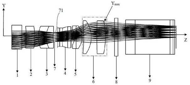
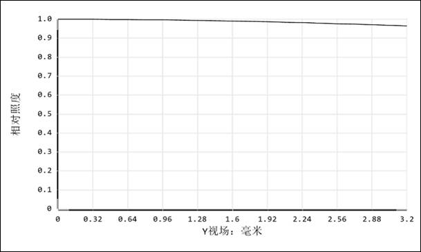
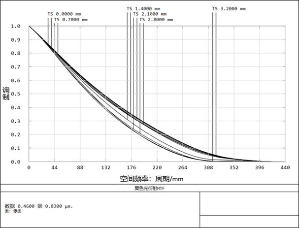
[0063] like Figure 1 to Figure 4 As shown, the liquid lens optical system provided by the first embodiment of the present invention includes a first lens group 2, a second lens group 3, a liquid lens 4, and a third lens group that are sequentially arranged along the optical axis from the object plane to the image plane 5. The fourth lens group 6 , the filter 8 and the prism unit 9 .

[0064] The first lens group 2 is a single lens, the surface of the first lens group 2 facing the object plane is concave, the surface of the first lens group 2 facing the image plane is convex, and the first lens group 2 has a positive optical focus degrees, its focal length is about 62mm.

[0065] The second lens group 3 is a doublet lens, the surface of the second lens group 3 facing the object plane is convex, the surface of the second lens group 3 facing the image plane is concave, and the second lens group 3 has a positive refractive power , its focal length is about 172mm.

[0066]The w...

no. 2 example

[0074] like Figure 5 to Figure 8 As shown, the liquid lens optical system provided by the second embodiment of the present invention includes a first lens group 2, a second lens group 3, a liquid lens 4, and a third lens group sequentially arranged along the optical axis from the object plane to the image plane 5. The fourth lens group 6 , the filter 8 and the prism unit 9 .

[0075] The first lens group 2 is a doublet lens, the surface of the first lens group 2 facing the object plane is concave, the surface of the first lens group 2 facing the image plane is convex, and the first lens group 2 has positive light power, its focal length is about 50mm.

[0076] The second lens group 3 is a single lens, the surface of the second lens group 3 facing the object plane is convex, the surface of the second lens group 3 facing the image plane is concave, and the second lens group 3 has positive refractive power, Its focal length is about 20mm.

[0077] The working voltage of the l...


PUM


Abstract

The present invention provides a liquid lens optical system, comprising a plurality of lens groups, the plurality of lens groups including a first lens group, a second lens group, a liquid lens, a first lens group, a second lens group, a liquid lens, a Three lens groups and a fourth lens group, each of which includes at least one lens; the liquid lens optical system satisfies the following conditions: |Y n+1 ‑Y n |<1mm; where, Y n+1 ‑Y n Represents the difference between the maximum heights of the light passing through two adjacent lens surfaces; the liquid lens optical system further includes a diaphragm, the diaphragm is provided with a light hole for the light to pass through, and the light passing on the diaphragm The hole is located between the second lens group and the liquid lens; the liquid lens optical system also satisfies the following conditions: |Z S -Z L |≥0.9mm. The invention also provides a camera lens.

Description

technical field [0001] The invention relates to the technical field of lenses, in particular to a liquid lens optical system and a camera lens. Background technique [0002] The lens can clearly capture images of different working distances by focusing. The focusing method of traditional zoom lenses (such as endoscope lenses) is based on mechanical movements, such as manually adjusting the knob (which can also be driven by a motor), Thereby, the lens or lens group in the lens is driven to move laterally along the optical axis, and by changing the optical interval between the lenses or between the lens and the camera chip, the shift of the imaging focus of the lens caused by the change of the working distance is compensated. [0003] The above-mentioned traditional focusing method requires more time to control the lens or lens group to move laterally along the optical axis, so the focusing speed is slow; Manually adjusting the knob to focus makes the operation inconvenient, ...

Claims


Application Information

Patent Timeline
Patent Type & Authority Patents(China)
IPC IPC(8): G02B3/14G02B13/00G02B15/04
CPCG02B3/14G02B15/04G02B13/00
Inventor 左惟涵陈琪琳李勇陈筱勇
Owner 深圳术为科技有限公司
Learn More