
High spectral resolution laser radar based on up-conversion

A lidar and hyperspectral technology, applied in the field of hyperspectral resolution lidar, can solve the problems of poor stability, reception field angle rejection ratio and other performance, high development cost and difficulty, and it is difficult to achieve a comparable absorption type frequency discriminator spectrum. Distinguish performance and other issues to achieve the effect of solving the development bottleneck problem, reducing the difficulty of development, and reducing the stability of use

Pending Publication Date: 2022-05-13
SHANGHAI INST OF TECHNICAL PHYSICS - CHINESE ACAD OF SCI
View PDF0 Cites 1 Cited by
  • Summary
  • Abstract
  • Description
  • Claims
  • Application Information

AI Technical Summary

Problems solved by technology

The design and use of the interference type spectral discriminator is not limited by the laser wavelength, but the performance of the interferometer itself is poor, such as the stability of the receiving field of view and the rejection ratio, it is difficult to achieve the spectral resolution performance comparable to the absorption type discriminator, and the development cost and The difficulty is relatively high; while the wavelength band used by the absorption spectrum discriminator is limited by the molecular characteristics, and the commonly used one is only the 532nm high spectral resolution laser radar based on the iodine molecular absorption cell. For the ultraviolet band that needs to be developed (such as 355nm ) and near-infrared (such as 1064nm) high-spectral resolution lidar, there is no suitable absorption spectrum discriminator

Method used


Image

  • High spectral resolution laser radar based on up-conversion
  • High spectral resolution laser radar based on up-conversion

Examples


Embodiment Construction

[0020] The present invention will be further described in detail below with reference to the accompanying drawings and embodiments. It should be noted that the following embodiments are intended to facilitate the understanding of the present invention, but do not limit it in any way.

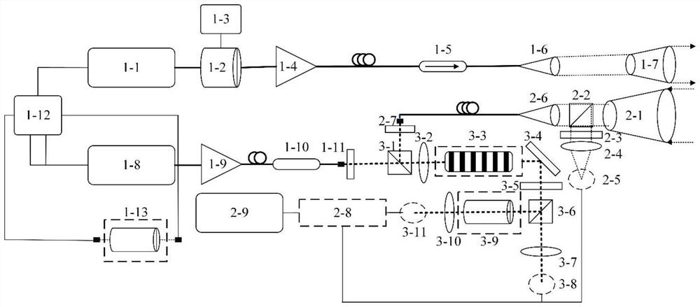
[0021] Such as figure 1 As shown, the high-spectral-resolution laser radar based on up-conversion can accurately measure the optical parameter characteristics of the aerosol in the atypical molecular absorption line band. In fact, the high-spectral-resolution lidar based on up-conversion in any band can be modified according to the technical solution of this embodiment without any creative work, so that it can also achieve the performance of multi-band high-spectral resolution lidar. Features.

[0022] The laser radar includes a laser transmitter module, a telescope receiver module, and a sum frequency and frequency discrimination module. Continuous wave single-frequency seed laser 1-1 is used...


PUM

PropertyMeasurementUnit
diameteraaaaaaaaaa

Abstract

The invention discloses a high-spectral-resolution laser radar based on up-conversion. The high-spectral-resolution laser radar comprises a laser transmitting module, a telescope receiving module and a sum frequency and frequency discrimination module. The laser transmitting module generates a single-frequency laser pulse signal, the telescope receiving module receives and detects a laser radar echo signal, and the sum frequency and frequency discrimination module enables the received laser radar echo signal and a single-frequency pump light signal to be subjected to sum frequency through a nonlinear crystal to generate a photon matched with a certain absorption spectral line of the frequency discrimination molecular absorption cell. Spectrum frequency discrimination is carried out through a frequency discrimination molecule absorption cell, photons generated by mie scattering are absorbed, an extra laser radar equation is obtained, and accurate solving of the laser radar equation is achieved. According to the invention, the wavelength of the high-spectral-resolution laser radar can be converted to the absorption spectral line of the common frequency discrimination molecular absorption cell for spectrum frequency discrimination, and the development difficulty of the multi-wavelength high-spectral-resolution laser radar is reduced.

Description

technical field [0001] The invention belongs to the technical field of laser radar remote sensing, and in particular relates to a laser radar with high spectral resolution based on an up-conversion principle. Background technique [0002] Atmospheric aerosols refer to solid or liquid particles such as dust and smoke suspended in the atmosphere with a diameter of 0.001 to 100 microns. As a minor component of the atmosphere, it not only plays an important role in radiation budget, air chemistry and hydrological cycle, but also affects environmental quality and public health. The origin and change, occurrence, residence time, physical properties, and chemical composition of aerosols are rapid processes in space and time. Lidar with high temporal and spatial resolution is a method that can efficiently provide global aerosol height observations, and can be a powerful supplement to passive remote sensing instruments. Among various lidars, high spectral resolution lidar (HSRL) is...

Claims


Application Information

Patent Timeline
Patent Type & Authority Applications(China)
IPC IPC(8): G01S7/483G01S7/481G01S17/88G01S17/95
CPCG01S7/483G01S7/481G01S17/88G01S17/95Y02A90/10
Inventor 沈雪孔伟陈滔乐文杰黄庚华舒嵘
Owner SHANGHAI INST OF TECHNICAL PHYSICS - CHINESE ACAD OF SCI
Learn More