
Automatic stratified sampling geological survey device

A geological survey and automatic layering technology, applied in the direction of sampling devices, etc., can solve problems that affect the accuracy of water sample analysis results, inaccurate sampling samples, and poor sampling results

Inactive Publication Date: 2022-05-13
王彦平
View PDF0 Cites 5 Cited by
  • Summary
  • Abstract
  • Description
  • Claims
  • Application Information

AI Technical Summary

Problems solved by technology

[0004] 1. The existing groundwater sampling device has poor sampling effect and inaccurate sampling when sampling groundwater, and cannot effectively perform layered sampling of groundwater at different depths, which is not conducive to hydrogeological investigation;
[0005] 2. When the existing groundwater sampling device samples groundwater, it cannot effectively seal the groundwater after sampling, resulting in the groundwater after sampling being easily mixed with groundwater at different depths, resulting in inaccurate sampling and affecting water samples the accuracy of the analysis results;
[0006] 3. The existing groundwater sampling device can only roughly estimate the sampling depth, but cannot accurately locate the sampling depth

Method used


Image

  • Automatic stratified sampling geological survey device
  • Automatic stratified sampling geological survey device
  • Automatic stratified sampling geological survey device

Examples


Embodiment 1

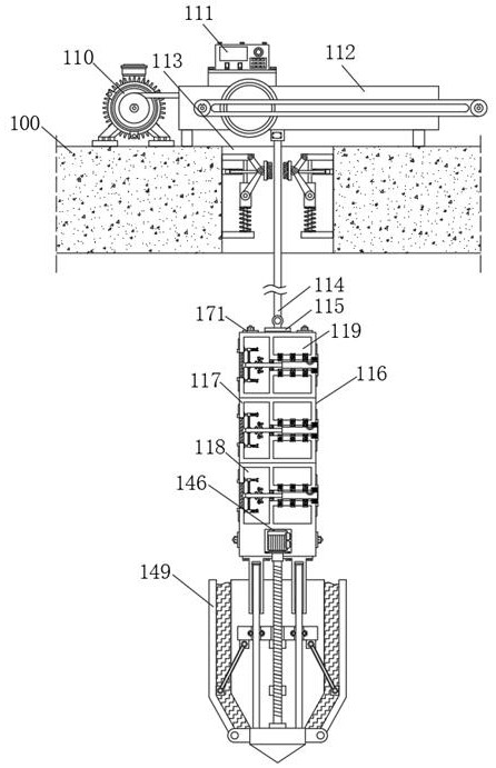
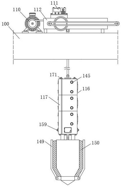
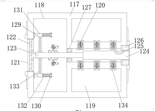
[0036] A geological survey device for automatic stratified sampling, including a device main body 100, used in this application, the first servo motor 110, the control panel 111, the second servo motor 146, the water pressure sensor 159 and the water level sensor 171 are all on the market The product that can be purchased directly, its principle and connection method are the prior art well known to those skilled in the art, so it will not be repeated here, the top of the device main body 100 is provided with a first servo motor 110 and a rope lowering frame 112, The top of the rope lowering frame 112 is fixedly equipped with a control panel 111, the top of the first servo motor 110 is provided with a rope lowering groove body 113, and the inside of the rope lowering frame 112 is provided with a rope body 114, and the rope body 114 extends to the lowering of the rope. In the inside of the tank body 113, the bottom end of the rope body 114 is fixedly equipped with a connection ba...

Embodiment 2

[0040] The same features of this embodiment and Embodiment 1 will not be repeated. The difference between this embodiment and Embodiment 1 is that in this embodiment, two installation round rods 129 are fixedly installed inside the installation cavity groove 118, and the installation circle One end of the rod 129 is fixedly installed with abutment plate 130, the outer surface of the installation round rod 129 is movably installed with a movable sleeve 131, and the outer surface of the installation round rod 129 is movably sleeved with a first return spring 132, and the first reset Both ends of the spring 132 are fixedly connected to the movable sleeve 131 and the abutting plate 130 respectively, and the side of the movable sleeve 131 close to each other is fixedly equipped with a connecting square bar 133, and the connecting square bar 133 is connected to the outer surface of the push rod body 123. Fixed connection, in actual use, through the setting of the above structure, the...

Embodiment 3

[0043] The same features of this embodiment and Embodiment 1 will not be repeated. The difference between this embodiment and Embodiment 1 is that in this embodiment, both sides of the inner wall of the connecting pipe 134 are provided with stabilizing chute 139, and the stabilizing chute 139 The insides of the slides are all slidably installed with stabilizing sliders 140, and the sides of the stabilizing sliders 140 that are close to each other are fixedly connected to the outer surface of the sealing abutting block 138. In actual use, through the setting of the above structure, the sealing abutting block 138 stability during use, both sides of the inner wall of the guide groove 155 are provided with ball grooves 157, and the inside of the ball groove 157 is rollingly installed with ball bodies 158. In actual use, through the setting of the above structure, the guide The usage loss generated between the groove 155 and the guide rod 156 is reduced.

[0044] Umbrella-shaped an...


PUM


Abstract

The invention discloses an automatic stratified sampling geological survey device which comprises a device body, a first servo motor and a rope lowering rack are arranged at the top end of the device body, a control panel is fixedly mounted at the top end of the rope lowering rack, and a rope lowering groove is formed in the top end of the first servo motor; a rope body is arranged in the rope lowering rack, the sampling water tank is driven by a first servo motor to sink, and in the process that the sampling water tank gradually sinks, after an elastic extrusion pad at one end of the sampling water tank is extruded by the water pressure of underground water, the sampling water tank is stressed to move rightwards; and a sampling push rod is pushed away from the interior of a push cavity groove by utilizing the push rod body, and an arc-shaped through groove is exposed out of the interior of a first sealing sleeve gasket, so that underground water with different depths is collected into a sample storage cavity through connecting pipelines by utilizing the arc-shaped through groove.

Description

technical field [0001] The invention relates to the technical field of hydrogeological survey, in particular to a geological survey device for automatic stratified sampling. Background technique [0002] Hydrogeological survey refers to the hydrogeological survey and research work to find out the hydrogeological conditions of an area. The purpose of hydrogeological survey is to grasp the cause, distribution and movement of groundwater and surface water. At present, the analysis of the cause, distribution and movement of groundwater mainly depends on the sampling of groundwater. [0003] The existing groundwater sampling devices mainly have the following problems: [0004] 1. The existing groundwater sampling device has poor sampling effect and inaccurate sampling when sampling groundwater, and cannot effectively perform layered sampling of groundwater at different depths, which is not conducive to hydrogeological investigation; [0005] 2. When the existing groundwater sam...

Claims


Application Information

Patent Timeline
Patent Type & Authority Applications(China)
IPC IPC(8): G01N1/10
CPCG01N1/10
Inventor 王彦平耿红红
Owner 王彦平
Learn More