
Heat exchange tube

A technology of heat exchange tubes and casings, which is applied in the direction of heat exchange equipment safety devices, tubular elements, heat exchange equipment, etc., can solve the problem of low input-output ratio, heat exchange tube vibration, and inability to use heat exchange efficiency metal heat exchangers and other problems to achieve the effect of solving the vibration

Active Publication Date: 2022-05-13
EVERBRIGHT ENVIRONMENTAL TECH CHINA CO LTD +2
View PDF7 Cites 0 Cited by
  • Summary
  • Abstract
  • Description
  • Claims
  • Application Information

AI Technical Summary

Problems solved by technology

[0002] Gas-gas heat exchanger is a mature heat exchange equipment widely used in chemical industry, transportation, energy, smelting, medical and other industries. However, due to its special flue gas composition in waste incineration power plants, the low-temperature 260°C) metal heat exchangers with high heat exchange efficiency cannot be used; even the existing new corrosion-resistant plastic heat exchangers only use various processing techniques to fix the plastic heat exchange tubes inside the heat exchanger, that is, The entire heat exchange equipment is a whole, and broken pipes and leaky pipes cannot be replaced, resulting in huge waste and low input-output ratio
[0003] At present, there is no technology or solution that solves the problem of heat exchange corrosion, sealing, thermal expansion, and vibration of heat exchange tubes.

Method used


Image

  • Heat exchange tube
  • Heat exchange tube
  • Heat exchange tube

Examples


Embodiment 1

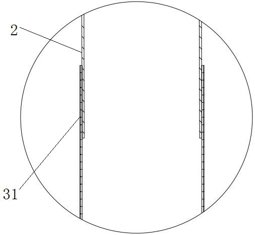
[0027] like figure 1 As shown, a heat exchange tube includes a pressure head section 1, a heat exchange section 2, a connecting section 3 and an anti-vibration section 4 from top to bottom.

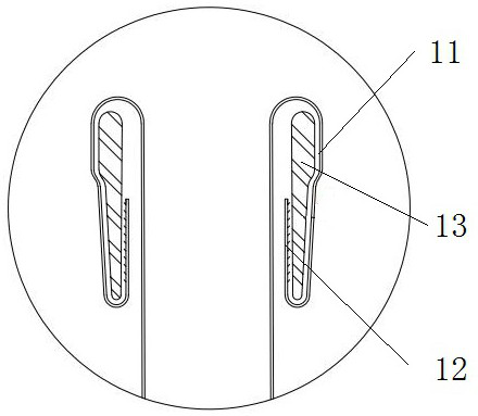
[0028] like figure 2 As shown, the pressure head section 1 is arranged on the outside of the heat exchange tube, and includes a first folded edge 11 , a second folded edge 12 and a pressure head metal 13 . The top end of the first folded edge 11 is connected with the top end of the heat exchange tube in an arc, and the included angle with the tube wall of the heat exchange tube is not less than 180°. The design of this folded edge can effectively prevent tearing. The second folded edge 12 is arranged between the tube wall of the heat exchange tube and the first folded edge 11, and its bottom end is arc-connected with the bottom end of the first folded edge 11, and the included angle with the first folded edge 11 is Not more than 30°, the design of this small angle can facilitate the pl...

Embodiment 2

[0034] On the basis of Embodiment 1, the sleeve 31 adopts a buckle design, such as Figure 4 As shown, the sleeve 31 is a looped tube, and the inner wall of the contact part of the looped tube and the heat exchange section 2 is provided with several ring-shaped buckles 311 in the circumferential direction. At this time, the downward pressure of the indenter metal satisfies:

[0035]

[0036] Among them, G 2 : downward pressure of the indenter metal when the ring tube is used, b: height of the ring ring, d: tube outer diameter of the heat exchange section, n: number of ring rings, c: width of the ring ring .


PUM


Abstract

The invention discloses a heat exchange tube, and belongs to the technical field of heat exchangers. The pressure head section is arranged on the outer side of the heat exchange tube, the top end of the first folded edge is in arc connection with the top end of the heat exchange tube, the included angle between the top end of the first folded edge and the tube wall of the heat exchange tube is not smaller than 180 degrees, the second folded edge is arranged between the tube wall of the heat exchange tube and the first folded edge, the bottom end of the second folded edge is in arc connection with the bottom end of the first folded edge, and the included angle between the bottom end of the second folded edge and the first folded edge is not larger than 30 degrees. The pressure head metal is attached to the inner walls of the first folding edge and the second folding edge; the connection section comprises a sleeve arranged at the bottom of the heat exchange section, and an inner hole of the sleeve is in interference fit with the heat exchange section. The bottom end of the third folded edge is in arc connection with the bottom end of the sleeve, the bottom of the third folded edge is axially parallel to the sleeve, the inner wall of the top of the third folded edge is in sealed connection with the outer wall of the sleeve, the middle of the third folded edge protrudes outwards, and the shockproof head is attached to the third folded edge and the inner wall of the sleeve. The invention has the characteristics of corrosion resistance, sealing, stability, immediate use after installation, and immediate replacement after damage.

Description

technical field [0001] The invention belongs to the technical field of heat exchangers, in particular to a heat exchange tube, and is especially suitable for gas-gas heat exchangers. Background technique [0002] Gas-gas heat exchanger is a mature heat exchange equipment widely used in chemical industry, transportation, energy, smelting, medical and other industries. However, due to its special flue gas composition in waste incineration power plants, the low-temperature 260°C) metal heat exchangers with high heat exchange efficiency cannot be used; even the existing new corrosion-resistant plastic heat exchangers only use various processing techniques to fix the plastic heat exchange tubes inside the heat exchanger, that is, The entire heat exchange equipment is a whole, and broken pipes and leaky pipes cannot be replaced, resulting in huge waste and low input-output ratio. [0003] At present, there is no technology or solution that solves the problem of heat exchange co...

Claims


Application Information

Patent Timeline
Patent Type & Authority Applications(China)
IPC IPC(8): F28F1/00F28F11/00
CPCF28F1/00F28F11/00F28F2265/30Y02P20/10
Inventor 杨宏伟胡利华鲁梦诗冯卓恒朱海淼夏文青王小柳任晓宇周民星
Owner EVERBRIGHT ENVIRONMENTAL TECH CHINA CO LTD
Learn More