
Bloom performance test system and test method of tdi detector

A technology of highlight overflow and test system, which is used in TV, electrical components, image communication, etc., and can solve the problem of inability to obtain imaging parameter performance test results.

Active Publication Date: 2021-01-05
CHANGCHUN INST OF OPTICS FINE MECHANICS & PHYSICS CHINESE ACAD OF SCI
View PDF4 Cites 0 Cited by
  • Summary
  • Abstract
  • Description
  • Claims
  • Application Information

AI Technical Summary

Problems solved by technology

[0003] The present invention aims to solve the problem that accurate imaging parameter performance test results cannot be obtained when TDI detectors have blooming due to unrelated testing methods in the industry at present, and provides a blooming performance testing system and testing method for TDI detectors

Method used


Image

  • Bloom performance test system and test method of tdi detector
  • Bloom performance test system and test method of tdi detector
  • Bloom performance test system and test method of tdi detector

Examples


specific Embodiment approach 1

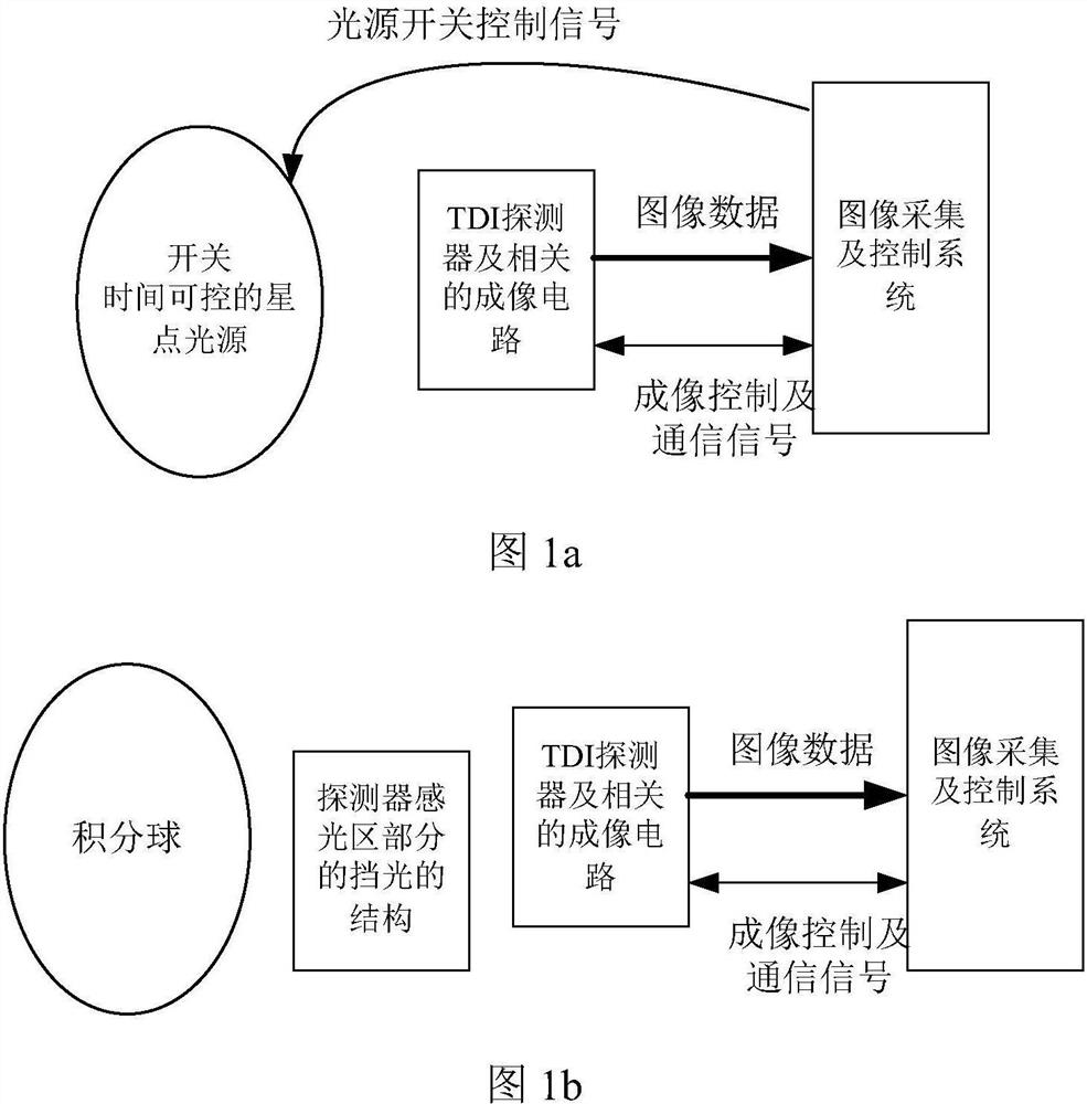
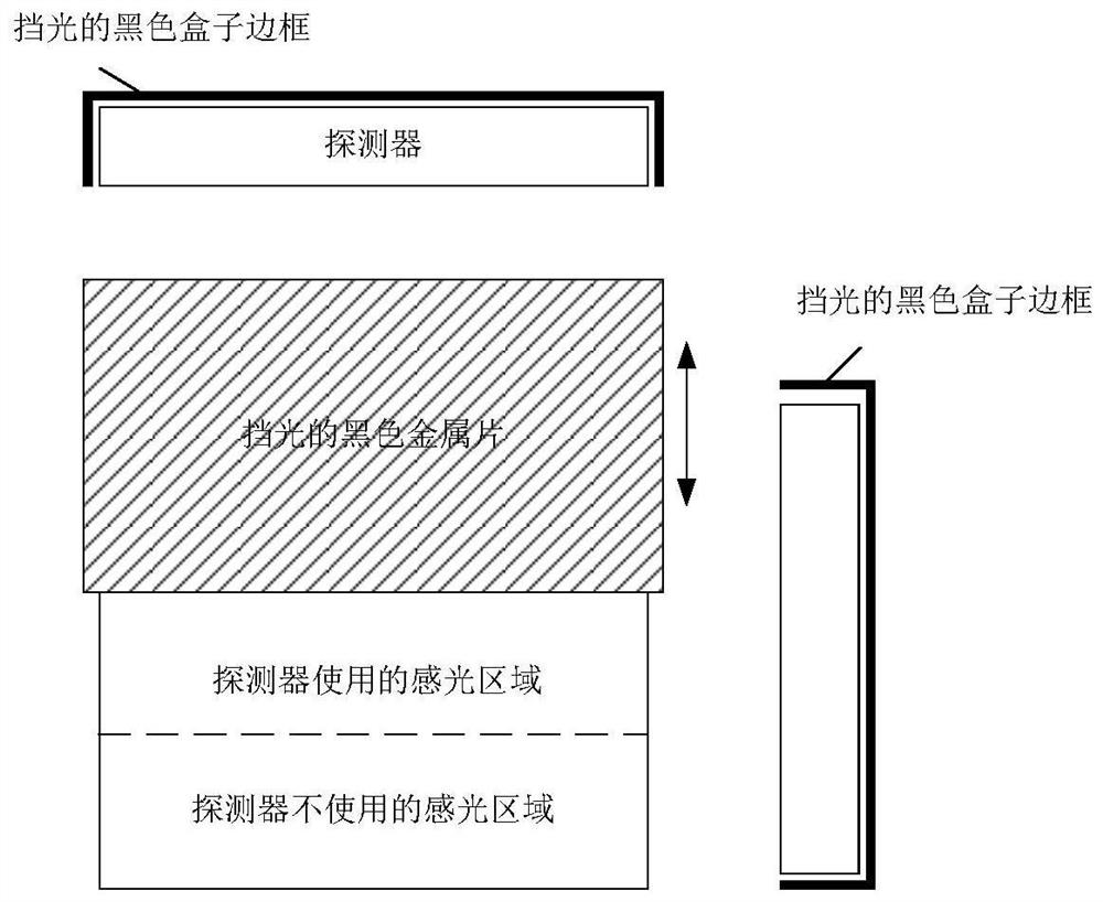
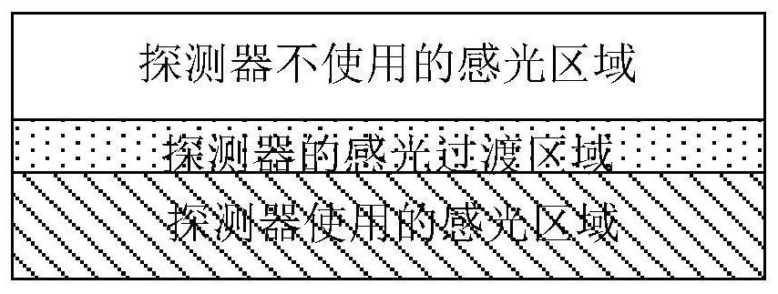
[0026] Specific implementation mode 1. Combination Figure 1 to Figure 3 Description of this embodiment, the TDI detector bloom performance test system mainly includes TDI detectors and related imaging circuits; light structure. It is mainly divided into CTE working mode test and TDI working mode with partial light blocking.

[0027] In the CTE area array mode, the star point light source with controllable switching time controlled by the image acquisition and control system is used as the illumination source of the TDI detector. The image acquisition and control system controls the TDI detector and related imaging circuits to generate Imaging control related signals, and communicate to obtain the imaging status; before the TDI detector starts to expose, turn on the star point light source with controllable switching time; when the TDI detector is exposed, turn off the star point light source with controllable switching time, and then Start the line-by-line transfer of charg...

specific Embodiment approach 2

[0029] Specific embodiment two, combine Figure 1 to Figure 3 Describe this embodiment, this embodiment is the test method of the TDI detector blown-out performance test system described in the first embodiment, the test method includes the blown-out performance detection under the CTE area array mode and the partial light-blocking TDI line array mode under Bloom performance detection.

[0030] The blooming performance detection process in the CTE area array mode is as follows:

[0031] A star point light source (small bright spot light source) with controllable switching time is used to form a small bright spot (a few pixels in size) after passing through the optical system, and the small bright spot is placed in the center of the photosensitive area; in the specified TDI series for level n (n max is the maximum available number of stages of the detector) to change the brightness of the star point, according to the saturated incident light energy I of the detector sat and ...


PUM


Abstract

Bloom performance test system and test method of TDI detector, in the field of TDI detector performance test, solves the problem that there is no relevant test method in the industry at present, which leads to the inability to obtain accurate performance test results of imaging parameters when TDI detector has a problem of blown light Problems include TDI detectors and imaging circuits, integrating spheres, star point light sources with controllable switching times, image acquisition and control systems, and light-shielding structures in photosensitive regions of detectors; The on-orbit simulation experiment was carried out; the anti-halation performance of the detector was evaluated in two ways: the area array CTE mode and the partial shading of the photosensitive area. Partially shading the photosensitive area to avoid judging whether the pixel is overflowed or not after saturation, to identify whether the saturation of the photosensitive area is caused by too much incident light energy or highlight overflow, and screen out TDI detector products that meet the application requirements.

Description

technical field [0001] The invention relates to the field of performance testing of TDI detectors, in particular to a method for testing the performance of highlight overflow of TDI detectors with high integral series. Background technique [0002] Since the anti-blooming structure inside the detector will reduce the fill factor and full well capacity, and may also affect the transfer function, most TDICCD or TDICMOS usually do not have anti-blooming (antiblooming) design. Bloom cannot be corrected by radioscaling due to its random nature. Users are most interested in ground features that contain a large amount of detailed information and have different brightness in each area. This part can be represented by a grayscale card or a uniform target superimposed with small bright spots; secondly, it is a relatively uniform radiation source used for radiation correction. Such as deserts, the moon, etc., this part is similar to the radiation calibration based on the integrating s...

Claims


Application Information

Patent Timeline
Patent Type & Authority Patents(China)
IPC IPC(8): H04N17/00
CPCH04N17/002
Inventor 余达刘金国梅贵薛旭成石俊霞齐洪宇张立华
Owner CHANGCHUN INST OF OPTICS FINE MECHANICS & PHYSICS CHINESE ACAD OF SCI
Learn More