Direct-driven breeze wind driven generator system
A wind turbine, direct-drive technology, used in wind turbines, wind turbines that are consistent with the wind direction, wind turbine control, etc. problems, to achieve the effect of improving anti-corrosion performance, improving unstable wind power, and reducing electromagnetic resistance
- Summary
- Abstract
- Description
- Claims
- Application Information
AI Technical Summary
Problems solved by technology
Method used
Image
Examples
Embodiment 1
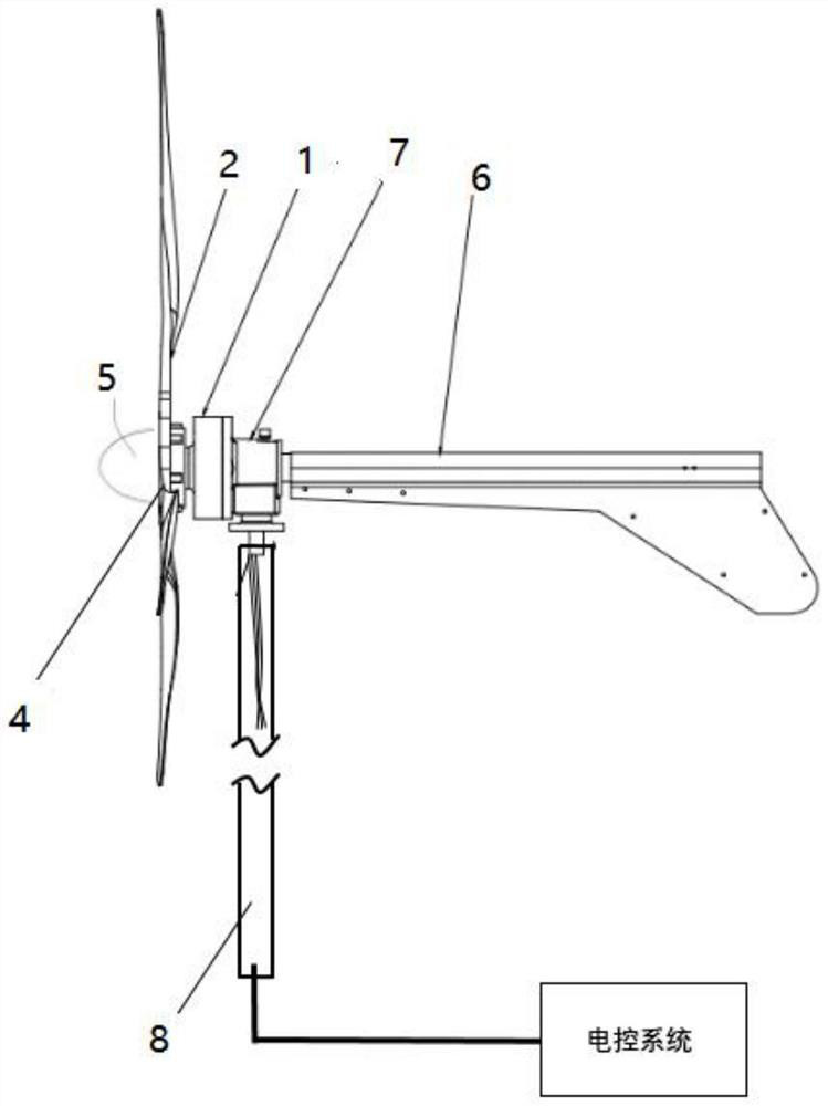
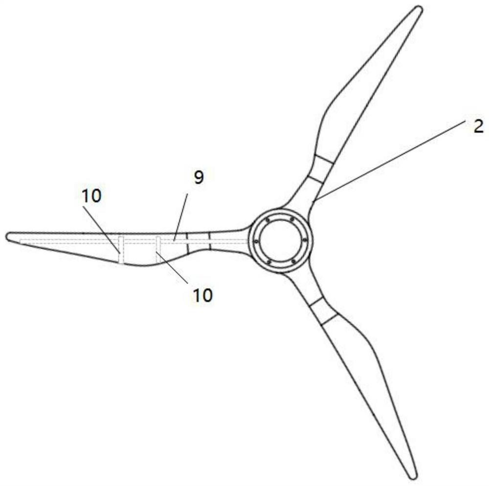
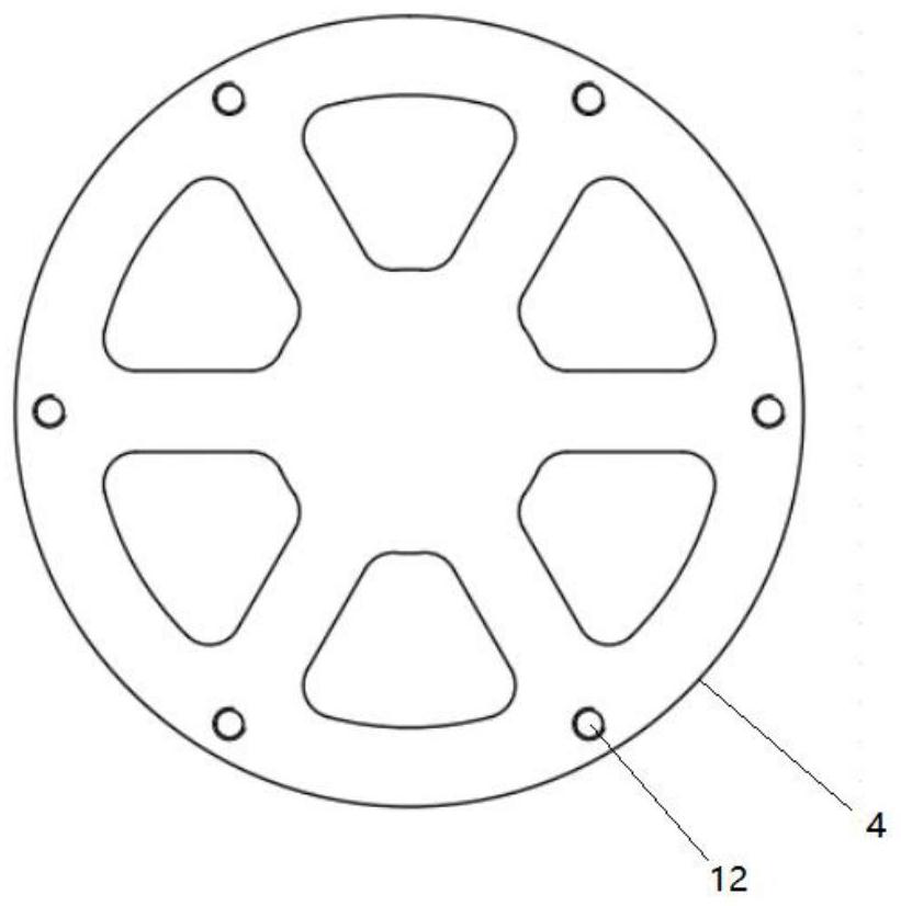
[0037] Please refer to the attached Figure 1-7 , Embodiment 1 of the present invention proposes a direct-drive breeze wind power generator system, which is characterized in that, as figure 1 As shown, it includes a wind power generator, an electric control system and an electrical storage device (not shown in the figure), and the wind power generator includes a generator cabin 1, an impeller 2, a hub 4, a shroud 5, a tail rudder 6, a generator The rear cover 7, the pole 8, the pole mounting seat, the impeller 2 is fixedly connected with the hub 4, the shroud 5 is installed on the impeller 2, and the generator compartment 1 is provided with an iron-free A permanent magnet alternator, the generator is fixedly connected to the hub 4 through the generator main shaft, an automatic braking device is arranged in the rear cover 7 of the generator, and the automatic braking device is used when the rotating speed of the impeller 2 Brake action is performed on the wind power generator ...
Embodiment 2
[0056] Please refer to the attached Figure 1-9 , Embodiment 2 of the present invention proposes a direct-drive breeze wind power generator system, which is basically the same structure as Embodiment 1 above, and is a further improvement on Embodiment 1. In this embodiment, as Figure 8As shown, the automatic braking device includes a rotational speed sensor (not shown in the figure), a controller (not shown in the figure), and a cylinder 13, and the cylinder 13 is provided with an air compressor 14, a main air cylinder 15, a pressure regulator valve 16 and piston push rod 17, the end of the piston push rod 17 is provided with a brake pad 18, the speed sensor is installed on the impeller 2, and the controller is electrically connected to the speed sensor and the cylinder 13 respectively. The controller is electrically connected to the power storage device.
[0057] During work, when the rotational speed sensor detects that the rotational speed of the impeller 2 of the wind po...
PUM
| Property | Measurement | Unit |
|---|---|---|
| thickness | aaaaa | aaaaa |
Abstract
Description
Claims
Application Information
 - Generate Ideas
- Intellectual Property
- Life Sciences
- Materials
- Tech Scout
- Unparalleled Data Quality
- Higher Quality Content
- 60% Fewer Hallucinations
Browse by: Latest US Patents, China's latest patents, Technical Efficacy Thesaurus, Application Domain, Technology Topic, Popular Technical Reports.
© 2025 PatSnap. All rights reserved.Legal|Privacy policy|Modern Slavery Act Transparency Statement|Sitemap|About US| Contact US: help@patsnap.com


