
Sliding end universal joint rod part push rod structure

A universal joint and rod technology, applied in the field of universal joints, can solve problems such as stuck, product falling off, and the retaining ring cannot be centered, so as to facilitate installation or disassembly and avoid irreplaceable effects.

Pending Publication Date: 2022-03-08
宁波德尚机械科技有限公司
View PDF0 Cites 0 Cited by
  • Summary
  • Abstract
  • Description
  • Claims
  • Application Information

AI Technical Summary

Problems solved by technology

[0003] The existing universal joint rod is directly connected to the retaining ring. After loading, the retaining ring cannot be centered, which may easily cause the product to fall off from the differential or get stuck.

Method used


Image

  • Sliding end universal joint rod part push rod structure
  • Sliding end universal joint rod part push rod structure
  • Sliding end universal joint rod part push rod structure

Examples


Embodiment Construction

[0016] Below in conjunction with specific embodiment, further illustrate the present invention. It should be understood that these examples are only used to illustrate the present invention and are not intended to limit the scope of the present invention. In addition, it should be understood that after reading the teachings of the present invention, those skilled in the art can make various changes or modifications to the present invention, and these equivalent forms also fall within the scope defined by the appended claims of the present application.

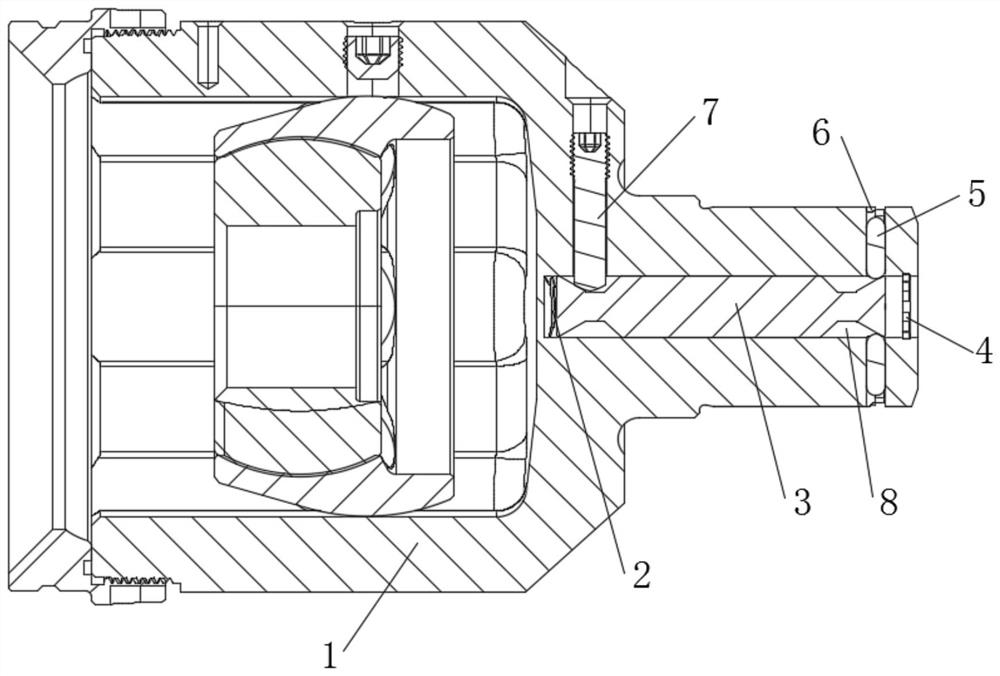
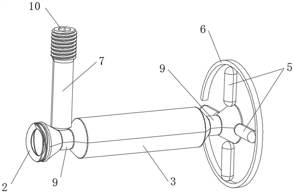
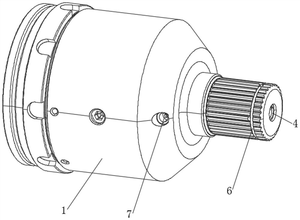
[0017] Embodiments of the present invention relate to a push rod structure of a sliding end universal joint rod, such as Figure 1-4 As shown, it includes a universal joint rod body 1 and a set screw 7 installed in the universal joint rod body 1. A laterally movable push rod 3 is installed inside one end of the universal joint rod body 1. The inside of the universal joint rod body 1 is located inside the push rod 3 and a sprin...


PUM


Abstract

The invention relates to a sliding end universal joint rod portion push rod structure which comprises a universal joint rod portion body and a fastening screw installed in the universal joint rod portion body, a transversely-moving push rod is installed in one end of the universal joint rod portion body, and a spring is installed in the universal joint rod portion body and located on the inner side of the push rod. An annular groove is formed in each of the two ends of the universal joint rod body, the section of each annular groove is trapezoidal, a plurality of tips are evenly arranged at the end of the universal joint rod body around the annular groove on the outer side, the portion, located on the outer side of the tips, of the end of the universal joint rod body is sleeved with a check ring, and the set screw is perpendicular to the push rod. And one end of the fastening screw is inserted into the annular groove on the inner side. The fastening screw is rotated, the push rod is driven to slide transversely, the inner wall of the annular groove extrudes the tip to control the check ring to be opened or folded, centering is convenient, and therefore a product can be conveniently mounted or dismounted, and the situation that the product cannot be replaced due to the fact that the check ring is clamped in the differential mechanism is avoided.

Description

technical field [0001] The invention relates to the technical field of universal joints, in particular to a push rod structure of a rod part of a sliding end universal joint. Background technique [0002] The universal joint is the universal joint, and the English name is universal joint. It is a component that realizes variable-angle power transmission. It is used to change the position of the transmission axis. It is the "joint" part of the universal transmission of the automobile drive system. The combination of universal joint and transmission shaft is called universal joint transmission. On vehicles with front-engine rear-wheel drive, the universal joint transmission device is installed between the output shaft of the transmission and the input shaft of the drive axle final drive; while the vehicle with front-engine front-wheel drive omits the drive shaft, the universal joint is installed Between the axle shaft of the front axle, which is responsible for both driving a...

Claims


Application Information

Patent Timeline
IPC IPC(8): F16D3/16
CPCF16D3/16
Inventor 袁阿勇杨世博杨文星
Owner 宁波德尚机械科技有限公司
Learn More