Electromagnetic actuator for variable valve lift camshaft and vehicle

An electromagnetic actuator, valve lift technology, applied in lift valves, machines/engines, non-mechanically actuated valves, etc., can solve the problems of large overall size, difficult layout, slow response time of electromagnetic actuators, etc. small effect

Active Publication Date: 2022-05-13
CHONGQING CHANGAN AUTOMOBILE CO LTD
View PDF5 Cites 0 Cited by
  • Summary
  • Abstract
  • Description
  • Claims
  • Application Information

AI Technical Summary

Problems solved by technology

[0006] The object of the present invention is to provide an electromagnetic actuator and a vehicle for a variable valve lift camshaft, which can solve the problems caused by the slow response time of the existing electromagnetic actuator, the simultaneous extension of two pin shafts and the large overall size. Arranging Difficult Issues

Method used


Image

  • Electromagnetic actuator for variable valve lift camshaft and vehicle
  • Electromagnetic actuator for variable valve lift camshaft and vehicle
  • Electromagnetic actuator for variable valve lift camshaft and vehicle

Examples


Embodiment Construction

[0021] The present invention will be described in detail below in conjunction with the accompanying drawings.

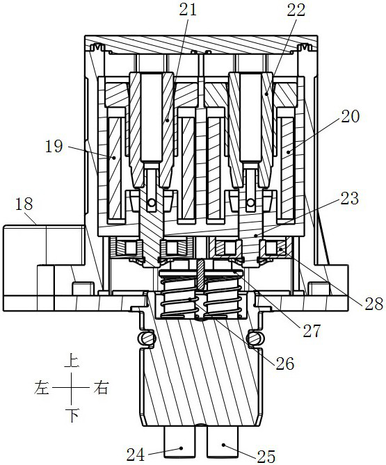
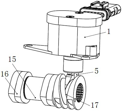
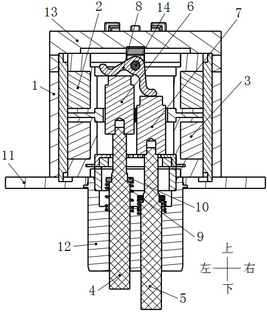
[0022] see figure 2 and image 3 , the shown electromagnetic actuator for the variable valve lift camshaft includes a housing 1, a solenoid arranged in the housing 1, a first push rod assembly 4 and a second push rod assembly arranged in parallel in the solenoid Push rod assembly 5 and reset assembly. The housing 1 includes a cylinder with an upper opening for installing a solenoid, a cover plate 13 for closing the upper opening of the cylinder, and a guide 12 connected below the cylinder.

[0023] The lower part of the housing 1 is provided with a mounting flange 11 extending radially outward, and the mounting flange 11 is provided with a mounting hole fixed to the vehicle body to provide an installation position for the assembly of the electromagnetic actuator on the vehicle body.

[0024] The solenoid includes a first solenoid 2 and a second solenoid 3 with co...


PUM


Abstract

The electromagnetic actuator comprises a shell, solenoids arranged in the shell, a first push rod assembly, a second push rod assembly and a reset assembly, the first push rod assembly and the second push rod assembly are arranged in the solenoids in parallel, and the solenoids comprise the first solenoid and the second solenoid which are opposite in winding direction. The upper ends of the first push rod assembly and the second push rod assembly are provided with a first magnetic core and a second magnetic core which move in the axial direction in response to energization of the solenoid respectively, the first magnetic core and the second magnetic core are made of permanent magnet materials and are opposite in magnetic field direction, and the lower ends of the first push rod assembly and the second push rod assembly penetrate through the shell and form sliding fit structures with the shell respectively. The reset assembly is used for pushing the first push rod unit and the second push rod unit back to the initial position after the solenoid is powered off. The problems that an existing electromagnetic actuator is slow in response time, left and right pin shafts cannot stretch out at the same time, and arrangement is difficult due to the large overall size can be solved.

Description

technical field [0001] The invention relates to the technical field of internal combustion engines, in particular to an electromagnetic actuator for a variable valve lift camshaft and a vehicle. Background technique [0002] In order to achieve both the fuel consumption and performance of the engine, the application of internal combustion engines in automobiles generally adopts variable valve lift technology, which uses a cam profile with a lower lift and a smaller wrap angle in the low-speed and small-load region of the engine. , so as to ensure the reduction of pumping loss and fuel consumption; in the high-speed and heavy-load area, a camshaft with a higher lift and a larger wrap angle is used to improve the charging efficiency and power performance. [0003] There are many technical means for modern engines to realize variable valve lift. One of the technical solutions is a system using an electromagnetic actuator and a sliding camshaft. When the system needs to switch t...

Claims


Application Information

Patent Timeline
Patent Type & Authority Applications(China)
IPC IPC(8): F01L9/21F01L13/00F01L3/10
CPCF01L9/21F01L13/0015F01L3/10F01L2009/2117F01L2009/2105F01L2009/2128
Inventor 林翰谢宗让周敬乔
Owner CHONGQING CHANGAN AUTOMOBILE CO LTD
Why Eureka
Try Eureka