Alloy shell part anodizing equipment with high sealing performance

A sealing and anodizing technology, which is applied in the field of alloys, can solve the problems of reducing the sealing effect and damage of the PTFE tape, and achieve the effect of preventing and strengthening the sealing effect

Pending Publication Date: 2022-05-13
唐光怀
View PDF0 Cites 0 Cited by
  • Summary
  • Abstract
  • Description
  • Claims
  • Application Information

AI Technical Summary

Problems solved by technology

[0004] In order to overcome the artificial winding of the PTFE tape, there is still a gap between the PTFE tape and the surface of the tooling thread, and the PTFE tape is not completely immersed in the thread groove. When it is rotated and inserted into the shell part, the thread in the shell part The structure will cause damage to the PTFE tape, thereby reducing the sealing effect. The invention provides a kind of anodizing equipment for alloy shell parts with strong sealing performance.

Method used


Image

  • Alloy shell part anodizing equipment with high sealing performance
  • Alloy shell part anodizing equipment with high sealing performance
  • Alloy shell part anodizing equipment with high sealing performance

Examples


Embodiment 1

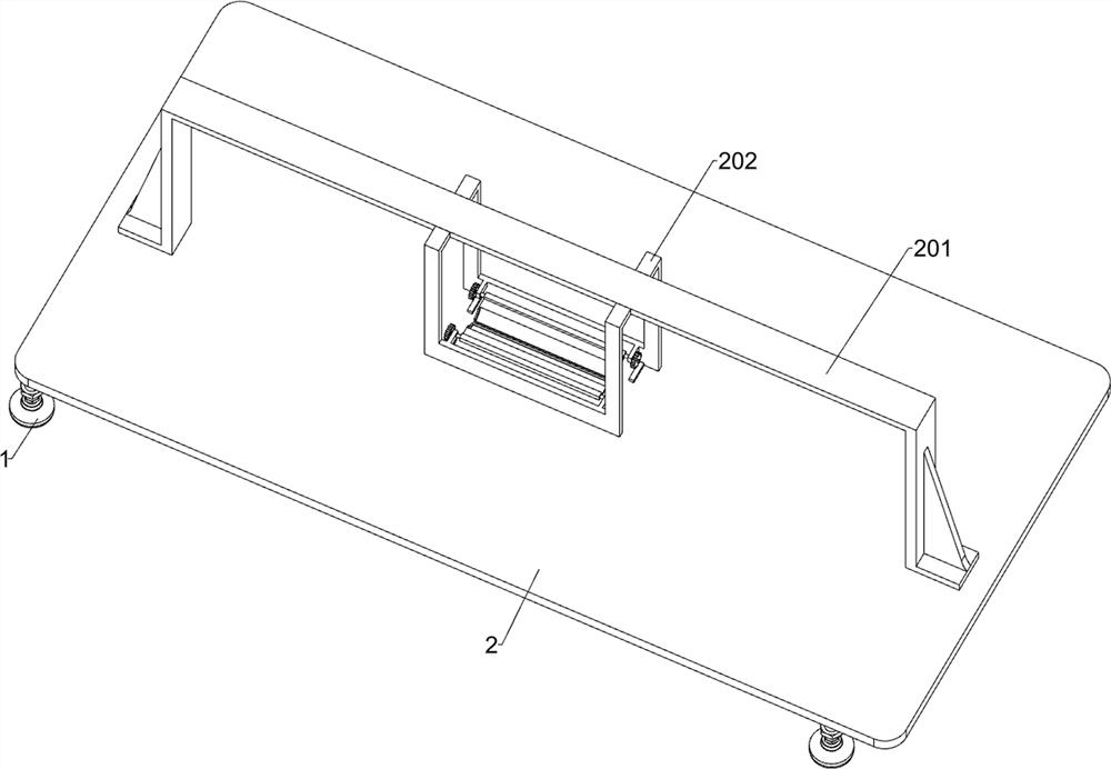
[0032]An anodizing equipment for alloy shell parts with strong sealing, such as Figure 1-9 As shown, it includes feet 1, a first mounting plate 2, a support unit and a sealed soaking unit; the top of the four feet 1 is connected to the first mounting plate 2; the upper middle of the first mounting plate 2 is connected to a support unit; The unit is connected with a sealed immersion unit.

[0033] The support unit includes a first mounting frame 201, a second mounting plate 202, a first transmission shaft 203, a convex plate 204, an arc plate 205 and a first spur gear 206; The mounting frame 201; the front side and the rear side of the first mounting frame 201 are fixedly connected with a second mounting plate 202 respectively; The lower parts of the opposite sides of the mounting plate 202 are respectively fixedly connected with two convex plates 204 arranged symmetrically, and the four convex plates 204 are located below the two first transmission shafts 203; the middle par...

Embodiment 2

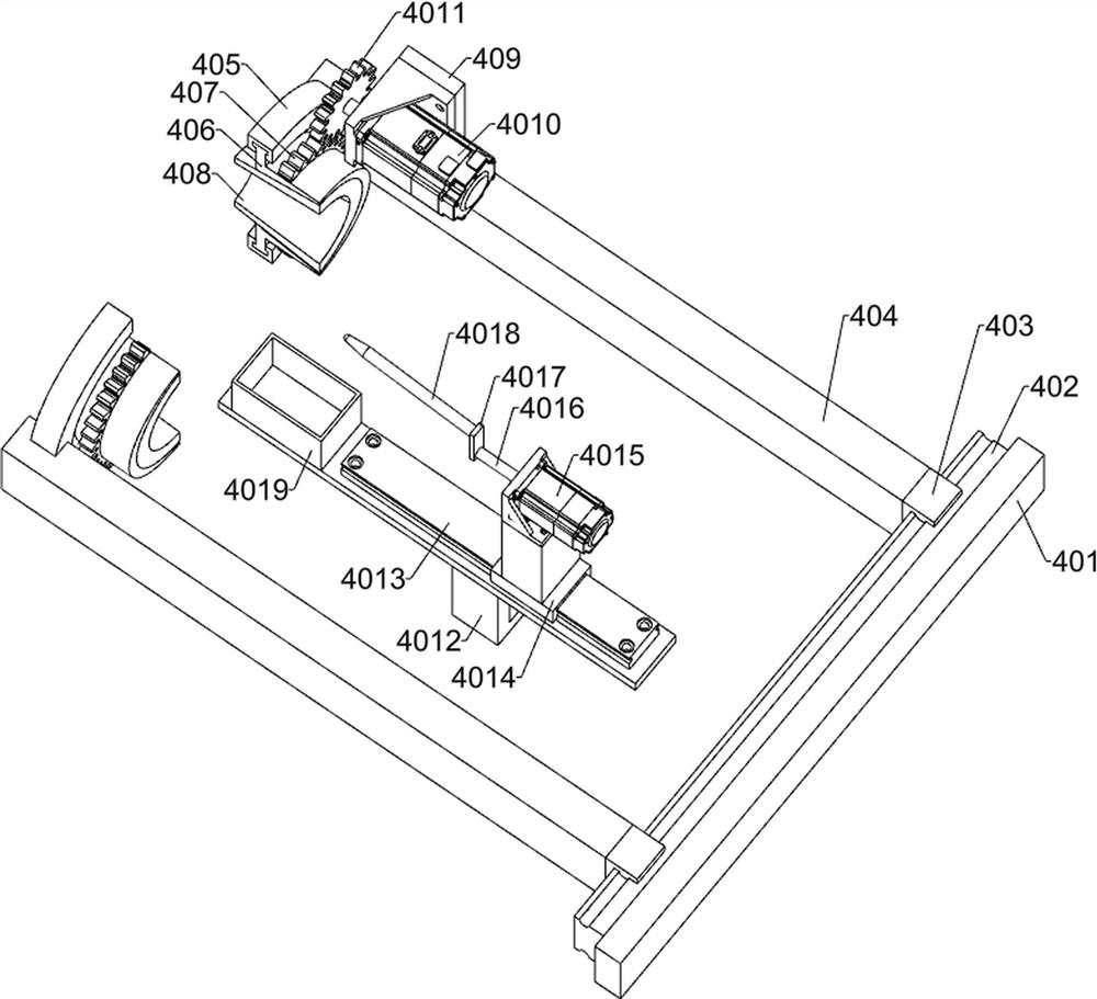
[0040] On the basis of Example 1, such as figure 1 with Figure 10-12 As shown, it also includes a seal cleaning unit; the first mounting plate 2 is connected with two seal cleaning units; the support unit is connected with two seal cleaning units, and the two seal cleaning units are symmetrically arranged left and right; The seal cleaning unit includes a fifth mounting plate 401, a fourth electric slide rail 402, a third electric slide block 403, a sixth mounting plate 404, an arc slide rail 405, an arc slide block 406, an arc gear 407, Arc sponge plate 408, the seventh mounting plate 409, the second motor 4010, the fifth spur gear 4011, the fifth mounting frame 4012, the second electric slide rail 4013, the fourth electric slider 4014, the third motor 4015, the second Transmission shaft 4016, connecting rod 4017, extrusion rod 4018 and second collection box 4019; the right side of the first mounting frame 201 is fixedly connected with the fifth mounting plate 401; the left ...


PUM


Abstract

The invention relates to the field of alloys, in particular to alloy shell part anodizing equipment with high sealing performance. The technical problems that after a polytetrafluoroethylene tape is manually wound, a gap still exists between the polytetrafluoroethylene tape and the threaded surface of a tool, the polytetrafluoroethylene tape is not completely sunken into a threaded groove, when the polytetrafluoroethylene tape is rotationally inserted into a shell part, a threaded structure in the shell part can cause damage to the polytetrafluoroethylene tape, and therefore the sealing effect is reduced are solved. According to the technical scheme, the alloy shell part anodizing equipment with the high sealing performance comprises a first mounting plate, a supporting unit and the like; a supporting unit is connected to the middle of the upper side of the first mounting plate. The anodizing treatment on the outer surface of the shell part is realized, the first screw rod and the conical rubber plug are inserted into the shell part to seal the shell part, then the shell part is immersed into corrosive liquid to be anodized, and a polytetrafluoroethylene tape is tightly wound on the outer surface of the first screw rod before insertion, so that the sealing effect is enhanced.

Description

technical field [0001] The invention relates to the field of alloys, in particular to an anodizing device for alloy casing parts with strong sealing performance. Background technique [0002] The shell part of the aerospace unlockable connection and separation device is made of titanium alloy, with a through hole on the inner surface. One section of the hole is a threaded structure, and the other end is a smooth surface structure. The outer surface of the shell part is required to be anodized, and the inner surface is not. Anodizing is permitted, and protection of the inner surface is required during anodizing. [0003] At present, threaded titanium alloy protective tooling and rubber plugs are usually used to seal the inner surface of the shell parts, and PTFE tape will be manually wrapped on the threaded surface of the tooling to enhance the sealing effect, but after the PTFE tape is wound manually , There is still a gap between the PTFE tape and the threaded surface of t...

Claims


Application Information

Patent Timeline
IPC IPC(8): C25D11/26
CPCC25D11/26
Inventor 唐光怀
Owner 唐光怀
Why Eureka
Try Eureka