Eureka AIR delivers breakthrough ideas for toughest innovation challenges, trusted by R&D personnel around the world.

Smoke exhaust and ventilation fire resisting damper with high sealing performance

A fire damper, high sealing technology, applied in lift valve, valve details, safety valve and other directions, can solve problems such as thermal deformation, deformation, and processing difficulty for workers, and achieve the effect of improving sealing effect and reducing air leakage.

Active Publication Date: 2016-03-16
ZHEJIANG JUYING FAN IND
View PDF7 Cites 4 Cited by
  • Summary
  • Abstract
  • Description
  • Claims
  • Application Information

AI Technical Summary

Problems solved by technology

During production, in addition to the problem that the flatness of the iron plate after forming process is required in the process, there is also the problem of thermal deformation due to welding process, which brings great processing difficulty to the workers who make the product. can not meet the requirements
Moreover, it will be deformed after being heated, which will cause a larger gap between the blade and the valve body, resulting in the air leakage of the fire protection valve not meeting the national standard GB15930-2007
[0003] Moreover, the existing fire dampers are sealed by fixing non-combustible strips such as asbestos on the inner wall of the valve body. However, the gap between the blades and the elastic deformation cannot be guaranteed, and it cannot be adjusted according to the temperature.

Method used


Image

  • Smoke exhaust and ventilation fire resisting damper with high sealing performance
  • Smoke exhaust and ventilation fire resisting damper with high sealing performance
  • Smoke exhaust and ventilation fire resisting damper with high sealing performance

Examples


Embodiment Construction

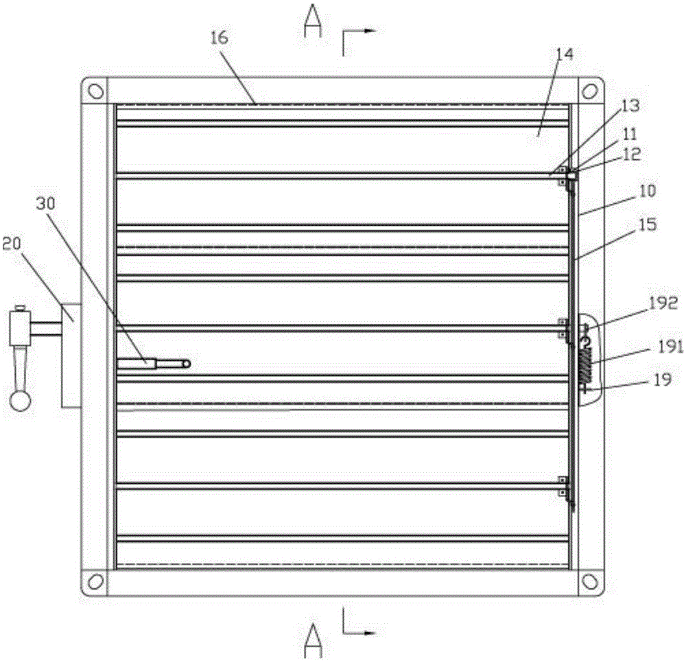
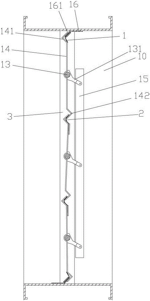
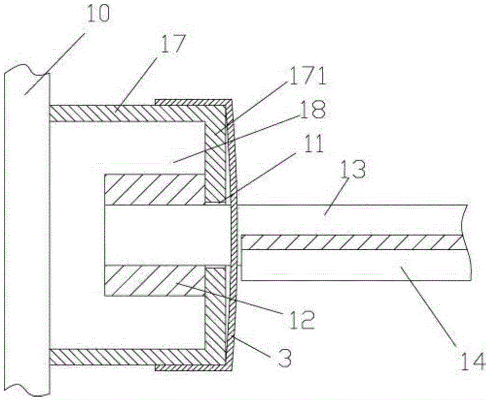
[0025] Examples, see e.g. Figure 1 to Figure 6 As shown, a high-seal smoke exhaust ventilation fire damper includes a valve body 10, and the valve body 10 is provided with an actuator 20, and the actuator 20 is connected with a temperature fuse 30. The left valve inside the valve body 10 The inner side wall and the right inner side wall are provided with a plurality of vane fixing grooves 11, and the left inner side wall or the right inner side wall of the valve body 10 at the vane fixing groove 11 is provided with a vane shaft sleeve 12, and the vane shaft 13 is inserted into the In the corresponding two blade bushings 12, the blade shaft 13 is provided with blades 14, and all the blades 14 are connected by blade connecting rods 15, and the top surface and the bottom surface of the valve body 10 are fixed with windshield strips 16, The windshield strip 16 is a long strip bent into an obtuse angle, one side of the obtuse angle is fixed on the top or bottom surface of the valv...


PUM

PropertyMeasurementUnit
Thicknessaaaaaaaaaa

Abstract

The invention discloses a smoke exhaust and ventilation fire resisting damper with high sealing performance. The smoke exhaust and ventilation fire resisting damper comprises a damper body; an executing mechanism is arranged on the damper body, and is connected with a temperature fuse; a plurality of blade fixing grooves are arranged on both the left inside wall and the right inside wall in the damper body; blade shaft sleeves are arranged on the blade fixing grooves; blade shafts are arranged in the two corresponding blade shaft sleeves in an inserting and sleeving manner; blades are arranged on the blade shafts, and are connected through a blade connecting rod; weather strips are fixed on the top surface and the bottom surface in the damper body, and are long strips bent to form obtuse angles; one side of each obtuse angle is fixed on the top surface or the bottom surface in the damper body, and the other side of each obtuse angle is a bevel side; and upper grooves protruding backwards are formed in the upper parts of the blades. After heated, side sealing plates, middle side sealing plates and arc-shaped sealing plates are clung to the blades, so that the sealing effect of the fire resisting damper is improved greatly, and the air leakage rate is reduced.

Description

Technical field: [0001] The invention relates to the technical field of fan equipment, and more specifically relates to a high-sealing smoke exhaust ventilation fire damper. Background technique: [0002] At present, general fire protection valves are welded by Q235 galvanized iron plates after forming. In production, in addition to the problem of good flatness of the iron plate after forming process in the process, there is also the problem of thermal deformation due to welding process, which brings great processing difficulty to the workers who make the product. cannot meet the requirements. Moreover, it will be deformed after being heated, which will cause a larger gap between the blade and the valve body, so that the air leakage of the fire protection valve cannot meet the national standard GB15930-2007. [0003] And what existing fire damper adopts is to be sealed by being fixed with asbestos and other non-combustible strips on the inner wall of the valve body, but it...

Claims


Application Information

Patent Timeline
IPC IPC(8): F16K1/226F16K1/22F16K1/36F16K17/38F16K31/70
CPCF16K1/223F16K1/2261F16K17/38F16K31/00
Inventor 蒋宁波石兴祥沈炳校
Owner ZHEJIANG JUYING FAN IND
Why Eureka
Eureka Blog
Learn More