Hot cathode spray gun and nano plasma spraying device and method

A plasma and hot cathode technology, applied in the direction of nanotechnology, nanotechnology, nanotechnology for materials and surface science, etc., can solve the problem of difficulty in fully entering the high temperature zone of the jet, the limitation of energy and space utilization, and the limitation of being sprayed Material loading rate and other issues to achieve the effect of stable flow, improved service life, improved stability and controllability

Pending Publication Date: 2022-05-13
ZHEJIANG UNIV
View PDF2 Cites 3 Cited by
  • Summary
  • Abstract
  • Description
  • Claims
  • Application Information

AI Technical Summary

Problems solved by technology

In the existing design, only one nozzle is used to spray the suspension into the 3D high temperature area. Either due to the relatively small inertia of the nanoparticles, it is often difficult to completely enter the jet high temperature area, or the loading rate is limited by the single-side nozzle (often only one nozzle) limit
This makes only a small part of the high-temperature region of the rotationally symmetric body of the 3D structure play the role of heating and melting the nanoparticles, which limits the energy and space utilization of the high-temperature plasma jet, and at the same time limits the spraying in the jet. Material Loading Rate

Method used


Image

  • Hot cathode spray gun and nano plasma spraying device and method
  • Hot cathode spray gun and nano plasma spraying device and method
  • Hot cathode spray gun and nano plasma spraying device and method

Examples


Embodiment Construction

[0042] The following will clearly and completely describe the technical solutions in the embodiments of the present invention with reference to the accompanying drawings in the embodiments of the present invention. Obviously, the described embodiments are only some, not all, embodiments of the present invention. Based on the embodiments of the present invention, all other embodiments obtained by persons of ordinary skill in the art without making creative efforts belong to the protection scope of the present invention.

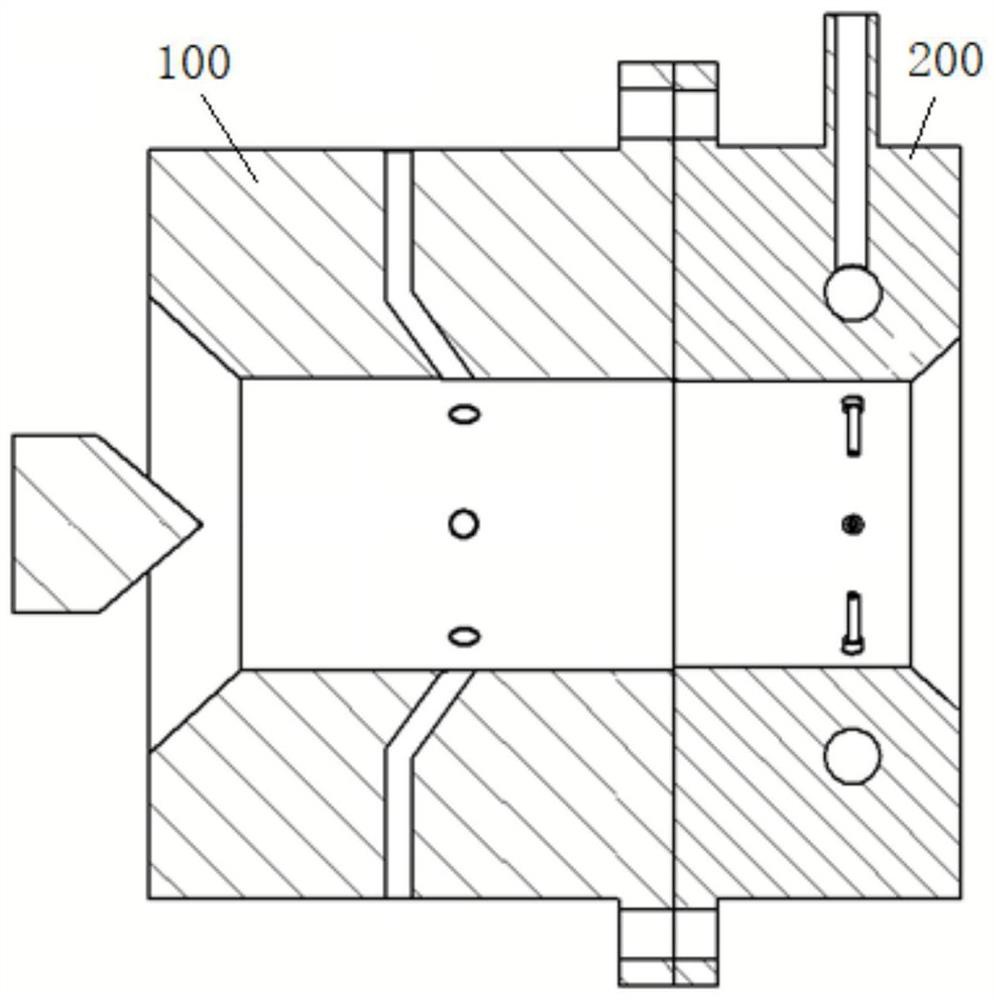
[0043] Such as figure 2 As shown, a nano-plasma spraying device includes a hot cathode spray gun 100 and a loader 200 . The hot cathode lance 100 is used to form the plasma jet and the loader 200 is used to provide the nanoparticle suspension. The butt joints of the hot cathode spray gun 100 and the loader 200 are connected by flanges, so as to realize the split design of the nano-plasma spraying device.

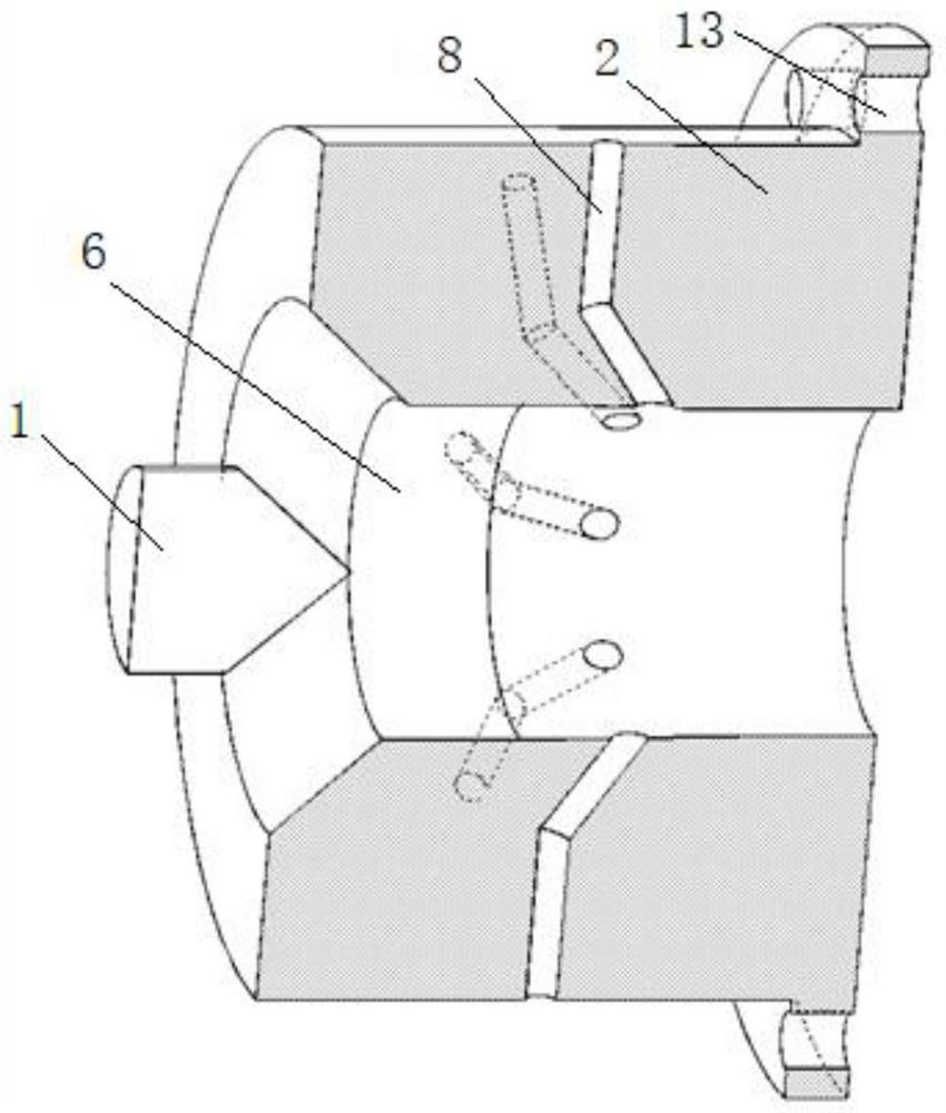
[0044] Such as image 3 As shown, similar to the p...


PUM

PropertyMeasurementUnit
diameteraaaaaaaaaa

Abstract

The hot cathode spray gun comprises a cathode with a conical emission structure and an annular anode, and bent channels which are evenly distributed and used for communicating the outside with an inner cavity of the anode are formed in the anode in the circumferential direction of the anode; the invention further discloses a nano plasma spraying device which comprises the hot cathode spray gun and a loader which is detachably connected with the hot cathode spray gun and used for providing nano particle suspension liquid. The loader is provided with an injection channel which is communicated with the inner cavity and is coaxial with the inner cavity; the invention further discloses a spraying method adopting the nano plasma spraying device. The device is simple, the loader is attached to one side of the anode of the spray gun, and a plurality of suspension nozzles are distributed around the jet flow, so that the nanoparticle suspension can be efficiently injected into the high-temperature plasma, and the loader can be prevented from being frequently replaced due to damage of the anode. The spray gun anode is protected from being ablated by high-temperature plasma through a flow control method introducing the Coanda effect.

Description

technical field [0001] The invention relates to the technical field of plasma spraying, in particular to a hot cathode spray gun, a nano-plasma spraying device and a method. Background technique [0002] Plasma spraying is a thermal spraying technology that uses high-temperature plasma jets as a heat source to heat metal or ceramic powder materials to a molten or semi-molten state, and then rapidly cools and solidifies after hitting the surface of the workpiece to form a certain thickness. Physically dense coating. If the metal or ceramic powder material adopts nanoscale powder material, the plasma spraying is also called nano plasma spraying. [0003] High temperature plasma gases are usually generated by means of arc discharge. For hot cathode plasma, the cathode is made of refractory metal, and the main carrier of the arc current - electrons leave the cathode in the form of thermal electron emission and enter the anode through the arc column area. The anode is made of ...

Claims


Application Information

Patent Timeline
Patent Type & Authority Applications(China)
IPC IPC(8): C23C4/134B82Y30/00
CPCC23C4/134B82Y30/00
Inventor 熊红兵彭学敏林建忠
Owner ZHEJIANG UNIV
Why Eureka
Try Eureka