
Plate punching and grinding device for intelligent manufacturing

An intelligent manufacturing and punching technology, applied in the field of plate punching, can solve the problems of manual time-consuming and laborious removal of metal discs, metal discs falling off, etc.

Pending Publication Date: 2022-05-13
张闽镛
View PDF0 Cites 2 Cited by
  • Summary
  • Abstract
  • Description
  • Claims
  • Application Information

AI Technical Summary

Problems solved by technology

[0002] The plate punching and grinding machine for intelligent manufacturing is mainly used for punching the plate. By placing the plate on the operating table of the plate punching and grinding machine for intelligent manufacturing, the punching head is driven by the lifting frame. The plate can be punched by descending, and the punching head can be driven to rotate by the driver, so that the inner wall of the hole on the plate can be polished. Intelligent manufacturing uses a plate punching and grinding machine to set the punching depth, and it is easy for the metal disc to be pressed into the plate with a slightly larger thickness and not completely fall off from the plate, resulting in the need for manual labor, time-consuming and laborious removal of the metal disc. When the piece is removed

Method used


Image

  • Plate punching and grinding device for intelligent manufacturing
  • Plate punching and grinding device for intelligent manufacturing
  • Plate punching and grinding device for intelligent manufacturing

Examples


Embodiment 1

[0035] Such as Figure 1 to Figure 10 Shown:

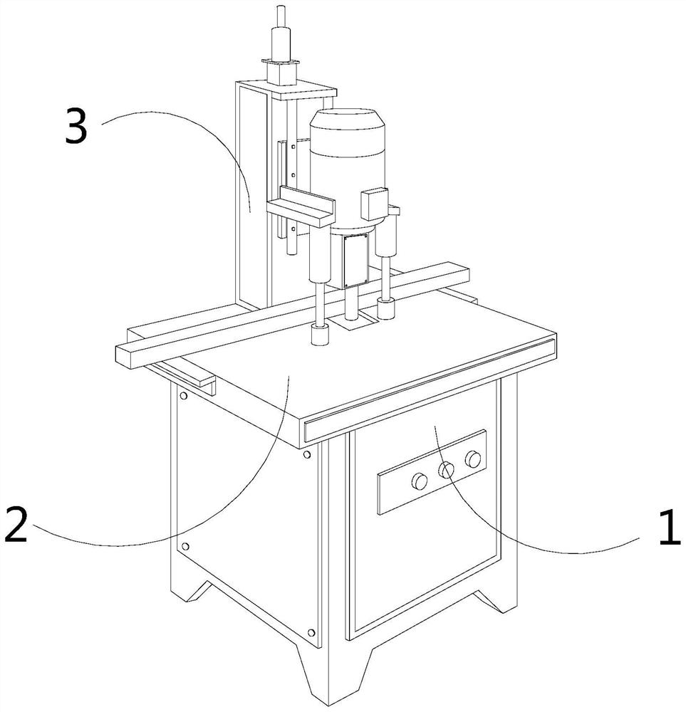
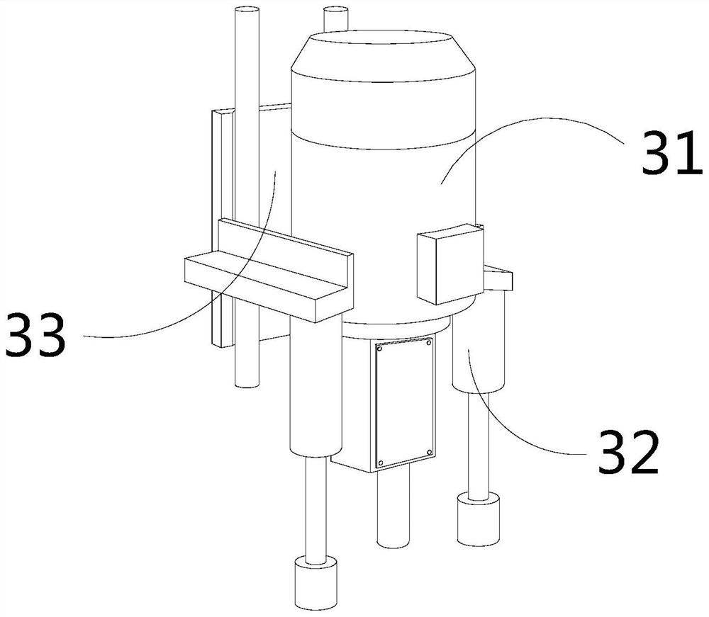
[0036] The invention provides a plate punching and grinding device for intelligent manufacturing, the structure of which includes a base 1, an operating table 2, and a processing frame 3, the bottom of the operating table 2 is connected to the upper end of the base 1, and the processing frame 3 is embedded The upper end of the operating table 2 is located behind; the processing frame 3 includes a punching mechanism 31, a positioning rod 32, and a lifting frame 33, and the punching mechanism 31 is fixed on the front end of the lifting frame 33, and the positioning rod 32 is fixed on the side position of punching mechanism 31.

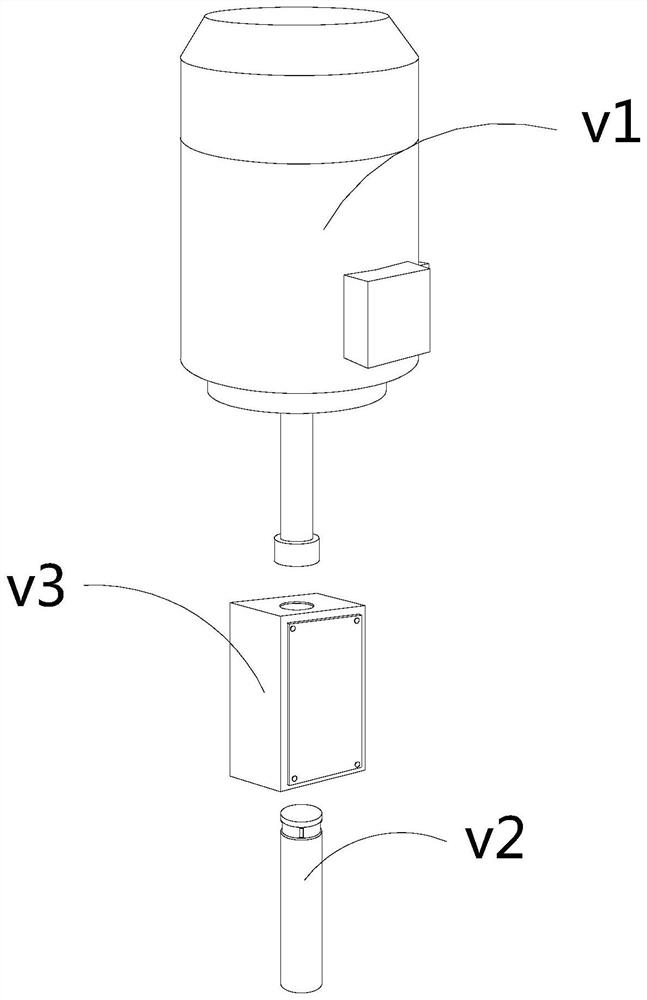
[0037] Preferably, the punching mechanism 31 includes a driver v1, a punching head v2, and a connecting frame v3, the top of the punching head v2 is embedded and connected to the bottom of the driver v1, and the top of the connecting frame v3 is connected to the bottom of the driver v1. The lower ends are ...

Embodiment 2

[0045] Such as Figure 11-Figure 14 Shown:

[0046] Preferably, the outer tube w3 includes an outer rod w31, a bottom ring w32, and a receiving ring w33, the bottom ring w32 is fixed at the bottom of the receiving ring w33, and the receiving ring w33 is connected to the bottom of the outer rod w31 , the diameter of the receiving ring w33 is greater than the thickness of the outer rod w31, and is larger than one-half of the thickness of the outer rod w31, so that the fine debris entering the interior of the outer rod w31 can fall on the inclined upper surface of the receiving ring w33.

[0047] Preferably, the bottom ring w32 includes an embedded groove y1, a ring body y2, and a vibration block y3. The embedded groove y1 is embedded in the inner position of the ring body y2. There are six vibrating blocks y3, which are distributed circularly on the ring body y2 under the cooperation of the six embedded grooves y1, and the clockwise rotation of the ring body y2 following the pu...

Embodiment 3

[0051] Such as Figure 15 Shown:

[0052] Preferably, the embedded groove y1 includes a block z1, a suction block z2, and a buffer surface z3. The suction block z2 is fixed on the right side of the block z1, and the buffer surface z3 is opposite to the left side of the block z1. connection, the suction block z2 is made of permanent magnet material, and the suction block z2 can generate an adsorption force on the mechanism made of steel, and the buffer surface z3 is made of soft natural latex, so that the collision surface between the block z1 and the mechanism can be Protect.

[0053] The detailed use method and function of this embodiment:

[0054] In the present invention, since the vibrating mass y3 inside the embedded groove y1 slides outward following the force of the punching head v2, the vibrating mass y3 can generate impact vibration on the inner wall of the ring body y2, but after the vibrating mass y3 slides outward It is difficult to reset. The magnetic suction b...


PUM


Abstract

The plate punching and polishing device for intelligent manufacturing structurally comprises a base, an operation table and a machining frame, the bottom of the operation table is connected with the upper end of the base, the machining frame is fixedly embedded in the rear position of the upper end of the operation table, and the machining frame can downwards slide out along a second sealing rod along with the gravity of the machining frame after punching is completed through a telescopic block; the annular body rotates clockwise along with the punching head, so that the vibration block rapidly impacts the inner wall of the embedded groove towards the outer side along the embedded groove, vibration can be generated, dust on the bearing ring can be gathered at the edge side attaching position of the outer pipe and the bearing ring, and therefore the effect that a metal wafer which does not completely fall off after a plate is punched is achieved is achieved. Therefore, fine chippings on the bearing ring can be discharged to a metal wafer generated by punching when the telescopic block is extruded and contracted, and after the punching head stops rotating, the suction block can be attracted by a steel material at the rear end of the embedded groove to automatically reset.

Description

technical field [0001] The invention relates to the technical field of plate punching, in particular to a plate punching and grinding device for intelligent manufacturing. Background technique [0002] The plate punching and grinding machine for intelligent manufacturing is mainly used for punching the plate. By placing the plate on the operating table of the plate punching and grinding machine for intelligent manufacturing, the punching head is driven by the lifting frame. The plate can be punched by descending, and the punching head can be driven to rotate by the driver, so that the inner wall of the hole on the plate can be polished. Intelligent manufacturing uses a plate punching and grinding machine to set the punching depth, and it is easy for the metal disc to be pressed into the plate with a slightly larger thickness and not completely fall off from the plate, resulting in the need for manual labor, time-consuming and laborious removal of the metal disc. When the pi...

Claims


Application Information

Patent Timeline
Patent Type & Authority Applications(China)
IPC IPC(8): B23P23/04B23Q11/00
CPCB23P23/04B23Q11/00B23Q11/0042
Inventor 张闽镛
Owner 张闽镛
Learn More