A detection device for tensile strength of solder bar
A detection device and solder bar technology, which is applied in the direction of measuring device, strength characteristics, and the use of stable tension/pressure test material strength, etc., can solve the problems of inconvenient feeding of solder bars, inconvenient hands-free operation, etc., to maintain stability Sex, increase the effect of clamping degree
- Summary
- Abstract
- Description
- Claims
- Application Information
AI Technical Summary
Problems solved by technology
Method used
Image

Examples
no. 1 example
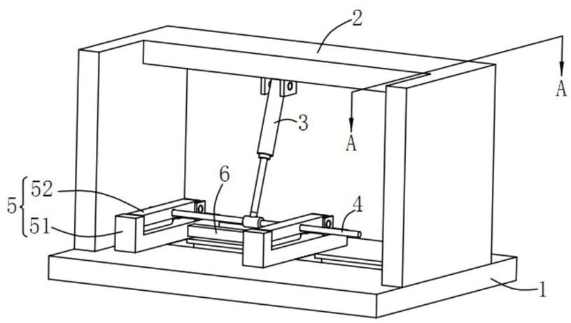
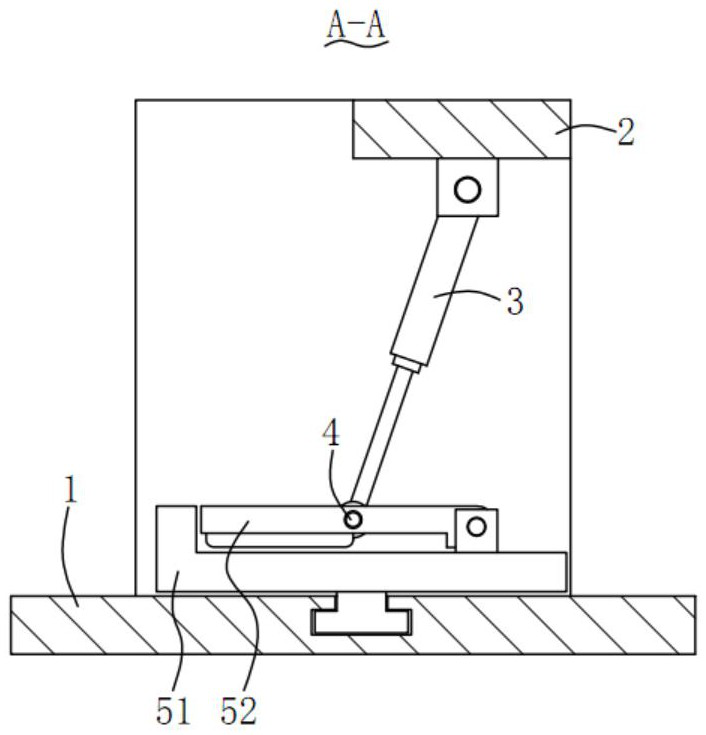
[0045] Please refer to Figure 1 to Figure 2 , in the first embodiment of the present invention, a detection device for tensile strength of a solder bar includes:
[0046] support 1;
[0047] an installation frame 2, the installation frame 2 is installed on the support 1;
[0048] The first telescopic element 3, one end of the first telescopic element 3 is rotatably mounted on the top of the mounting frame 2;
[0049] a transmission shaft 4, the transmission shaft 4 is mounted on the other end of the first telescopic member 3;
[0050] Two clamp assemblies 5, the clamp assembly 5 includes a fixed clamp plate 51 and a flip clamp plate 52, the bottom end of the fixed clamp plate 51 is slidably connected to the support 1, and one end of the flip clamp plate 52 is connected to the fixed clamp plate 52. The splints 51 are connected in rotation, wherein the two fixed splints 51 are connected by a second telescopic piece 6 , and the two ends of the transmission shaft 4 respectivel...
no. 2 example
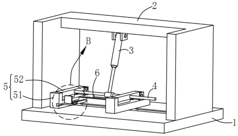
[0075] see image 3 and Figure 5 , based on the testing device for tensile strength of solder bars provided by the first embodiment of the present application, the second embodiment of the present application proposes another testing device for tensile strength of solder bars. The second embodiment is only a preferred mode of the first embodiment, and the implementation of the second embodiment will not affect the independent implementation of the first embodiment. Specifically, the difference between the testing device for tensile strength of solder bars provided by the second embodiment of the present application is that the testing device for tensile strength of solder bars further includes a pusher assembly 7; the pusher assembly 7 includes a limit plate 71, a third telescopic piece 72, a sliding frame 73 and a push plate 74, the limit plate 71 is fixedly installed on one of the fixed splints 51, and the two ends of the third telescopic piece 72 are respectively connecte...
no. 3 example
[0100] Please refer to Figures 6 to 9 , based on the testing device for tensile strength of solder bars provided by the first embodiment of the present invention, the third embodiment of the present invention proposes another testing device for tensile strength of solder bars. The third embodiment is only a preferred mode of the first embodiment, and the implementation of the third embodiment will not affect the independent implementation of the first embodiment.
[0101] Specifically, the difference between the testing device for tensile strength of solder bars provided by the third embodiment of the present invention is that the testing device for tensile strength of solder bars further includes a pusher assembly 7; the pusher assembly 7 includes A sliding frame 73 and a push plate 74 , a push plate 74 is fixedly installed on the sliding frame 73 ; a limit chute 511 is provided on any of the fixed splints 51 , and the sliding frame 73 and the limit chute 511 The two ends o...
PUM
| Property | Measurement | Unit |
|---|---|---|
| thickness | aaaaa | aaaaa |
Abstract
Description
Claims
Application Information
 - R&D
- Intellectual Property
- Life Sciences
- Materials
- Tech Scout
- Unparalleled Data Quality
- Higher Quality Content
- 60% Fewer Hallucinations
Browse by: Latest US Patents, China's latest patents, Technical Efficacy Thesaurus, Application Domain, Technology Topic, Popular Technical Reports.
© 2025 PatSnap. All rights reserved.Legal|Privacy policy|Modern Slavery Act Transparency Statement|Sitemap|About US| Contact US: help@patsnap.com