
Stator and motor

A stator and motor technology, applied in the directions of transportation and packaging, winding, electric components, etc., can solve the problems of difficult assembly, complex connection shape, etc., and achieve the effect of improving the ease of manufacturing and realizing short-pitch winding

Pending Publication Date: 2022-05-06
NIDEC CORP
View PDF9 Cites 0 Cited by
  • Summary
  • Abstract
  • Description
  • Claims
  • Application Information

AI Technical Summary

Problems solved by technology

[0005] Compared with coils formed of wires, the above-mentioned plate coils have a problem of difficulty in assembly when the shape of the connection between the slits becomes complicated

Method used


Image

  • Stator and motor
  • Stator and motor
  • Stator and motor

Examples


no. 1 approach >

[0021]

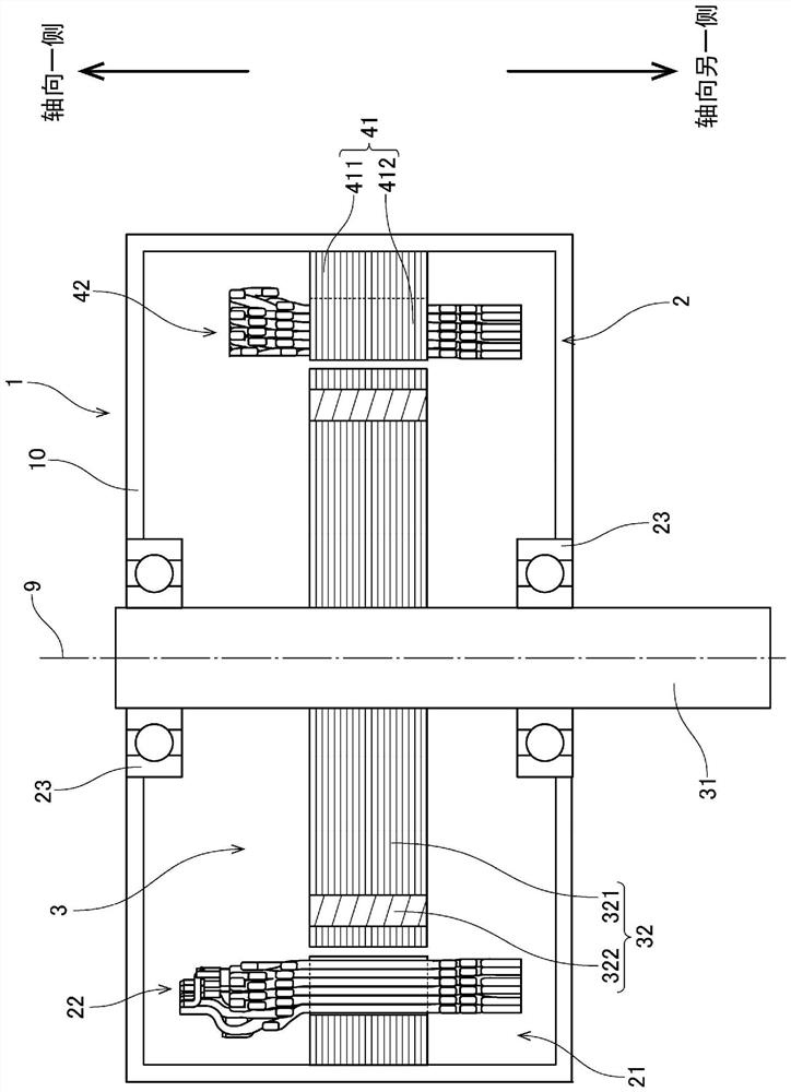
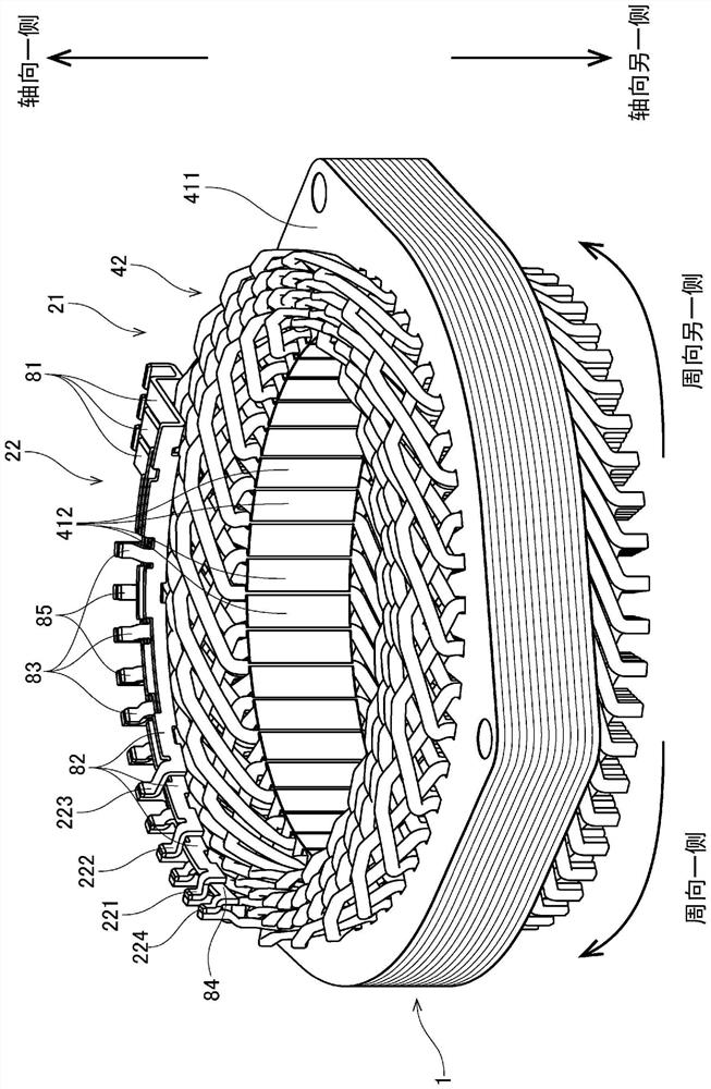
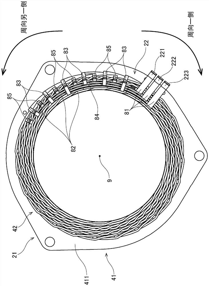
[0022] figure 1 It is a schematic cross-sectional view of the motor 1 having the stator 21 according to the first embodiment of the present invention. figure 2 It is a perspective view of the stator 21 and the bus bar part 22. also, image 3 It is a plan view of the stator 21 and the bus bar part 22 viewed from one side in the axial direction.

[0023] The motor 1 is a traction motor installed in a vehicle such as an electric vehicle or a plug-in hybrid vehicle, and outputs a driving force for driving the vehicle. However, the motor 1 of the present invention may also be a motor for purposes other than a traction motor. For example, it may be a motor that is installed in air blowers, home electric appliances, medical equipment, industrial large equipment, etc., and outputs a driving force.

[0024] Such as figure 1 As shown, the motor 1 has a motor housing 10 , a stationary part 2 and a rotating part 3 . The motor cover 10 is a frame housing at least part of ...


PUM


Abstract

This stator is provided with: a stator core having a plurality of pole teeth; a plurality of pins having an action portion extending in the axial direction in a slot between the pole teeth; and a plurality of bus bars electrically connected with the plurality of pins. In each cutting groove, the acting parts are arranged in multiple layers in the radial direction. The plurality of pins have: a first pin (51) and a second pin (52) each having two acting parts disposed across the pole teeth and a connecting part connecting the acting parts in the circumferential direction; and a third pin (53) connected to the bus bar. The acting portion of the second pin (52) is disposed in either the outermost layer or the innermost layer of the cut groove, and the acting portion of the third pin is disposed in either the outermost layer or the innermost layer of the cut groove or the other. The number of pole teeth strided by the second pins is two more than the number of pole teeth strided by the first pins. By disposing the pins in the above manner, short-pitch winding can be realized, and the ease of manufacture of the motor including the plate coil can be improved.

Description

technical field [0001] The invention relates to a stator for a motor and a motor. This application is based on Japanese Invention Patent Application No. 2019-179971 filed on September 30, 2019. This application claims the benefit of priority to the above-mentioned application. The entire content is incorporated in this application by reference. Background technique [0002] Conventionally, vehicles such as electric vehicles and plug-in hybrid vehicles are equipped with drive devices that use motors as power sources. A coil formed by bending an elongated plate-shaped conductor plate (hereinafter referred to as "plate coil") may be used in a motor with a large output power, such as a traction motor that outputs driving force for vehicle running. For example, Japanese Laid-Open Publication No. 2012-16195 describes a conventional motor using the above-mentioned coils. [0003] Patent Document 1: Japanese Laid-Open Publication No. 2012-16195 Contents of the invention [00...

Claims


Application Information

Patent Timeline
IPC IPC(8): H02K3/12H02K3/04H02K3/48H02K15/04
CPCH02K3/12H02K3/04H02K3/48H02K15/0435Y02T10/64H02K3/50H02K3/28H02K2203/09
Inventor 高田响上田智哉桧皮隆宏
Owner NIDEC CORP
Learn More