
Connector assembly and plug and socket locking connection structure

A technology of plug, socket and connection structure, which is applied to the parts, connections, and two-part connection devices of connection devices, etc., can solve the problems of large space occupation, inability to meet the requirements of miniaturization of servo motor installation space, etc., so as to reduce the space occupation. Space, realize the effect of miniaturization of installation and size reduction

Pending Publication Date: 2022-05-06
CHINA AVIATION OPTICAL-ELECTRICAL TECH CO LTD
View PDF1 Cites 0 Cited by
  • Summary
  • Abstract
  • Description
  • Claims
  • Application Information

AI Technical Summary

Problems solved by technology

[0005] The purpose of the present invention is to provide a plug and socket locking connection structure to solve the problem that the existing plug and socket locking connection structure occupies a large space in the direction of plug and socket insertion, and cannot meet the needs of miniaturization of servo motor installation space Problem; Correspondingly, the object of the present invention is to provide a connector assembly to solve the technical problem that the connector assembly in the prior art occupies a large space and cannot meet the needs of miniaturization of the servo motor installation space

Method used


Image

  • Connector assembly and plug and socket locking connection structure
  • Connector assembly and plug and socket locking connection structure
  • Connector assembly and plug and socket locking connection structure

Examples


specific Embodiment 1

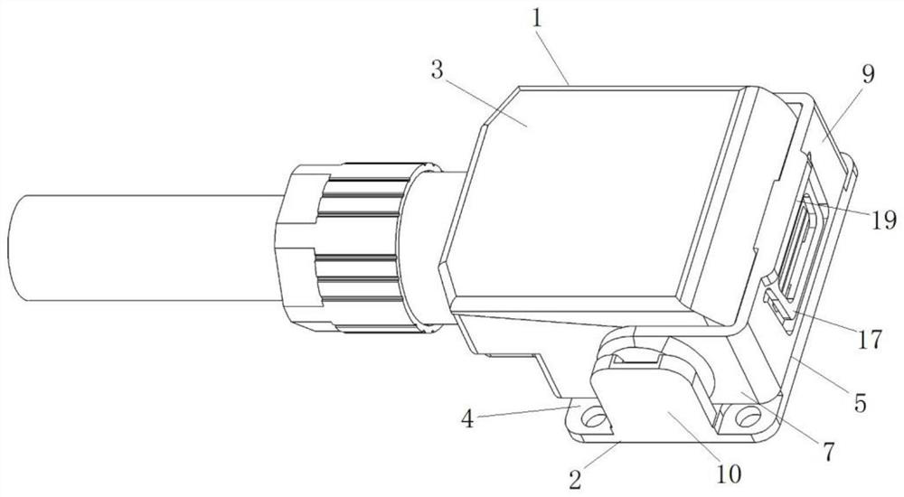
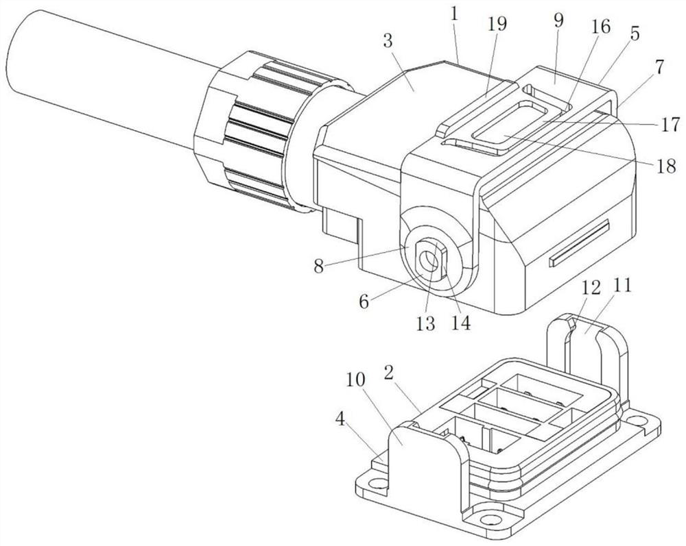
[0071] likefigure 1 and figure 2 As shown, the connector assembly includes a plug 1 and a socket 2. The plug 1 includes a plug housing 3, and the socket 2 includes a socket housing 4. 2 Locking connection structure with locking fit.

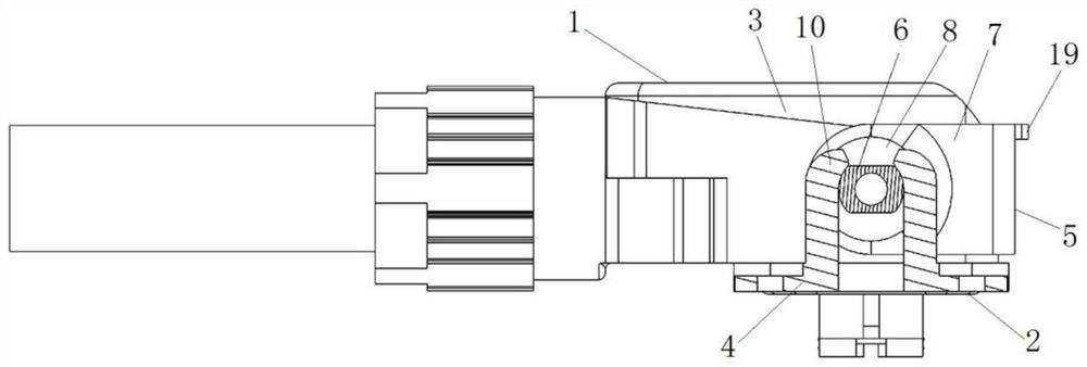
[0072] The locking connection structure includes a locking wrench 5 and a locking arm 10 . The locking wrench 5 is rotated and assembled on the plug housing 3. During the rotation of the locking wrench 5 relative to the plug 1, the locking wrench 5 has a locking position for locking the plug 1 and the socket 2, and also has a function for making the plug 1 and the socket 2 lock together. Unlock bit for socket 2 unlock. Specifically, such as figure 2 and Figure 4 As shown, the locking wrench 5 is a U-shaped structure, and the locking wrench 5 includes a rotating arm 7 formed by two side walls of the U-shaped structure. Extending in the direction perpendicular to the rotation axis, the two rotation arms 7 are provided with through holes cor...

specific Embodiment 2

[0085] The difference with the specific embodiment 1 is that the minor axis dimension of the locking cam is equal to the notch width dimension, and the major axis dimension of the locking cam is smaller than the diameter dimension of the arc groove wall surface. The structure of the groove can also restrict the locking cam from coming out of the locking groove when the plug and socket are inserted in place and the locking wrench is rotated to the locking position, so as to realize the effective locking of the plug and the socket.

specific Embodiment 3

[0087] The difference from the specific embodiment 1 is that the outer contour of the locking cam is elliptical, the locking groove is a circular groove, and in the vertical insertion direction, the locking groove is a through groove, and the notch is facing the insertion direction. The diameter dimension of the circular groove is equal to the major axis dimension of the locking cam, and the notch width dimension is greater than the minor axis dimension of the locking cam.


PUM


Abstract

The invention relates to a connector assembly and a plug and socket locking connection structure. The connector assembly comprises a plug, a socket and a locking connection structure for locking the plug and the socket, the locking connection structure comprises a locking wrench, the locking wrench has a locking position and an unlocking position in the rotating process, a locking cam is arranged at the position of the rotating axis of the locking wrench, the locking connection structure further comprises a locking arm, a locking groove is formed in the locking arm, and the locking arm is connected with the locking cam. The locking groove is a closing groove; when the locking wrench is located at the unlocking position, the locking cam can enter the locking groove from the notch, and when the locking wrench is located at the locking position, the locking cam cannot be separated from the locking groove in the insertion direction, and locking of the plug and the socket is achieved. As the locking cam is arranged at the position of the rotating axis of the locking wrench, the size of the locking wrench in the inserting direction when the locking wrench is located at the locking position can be effectively reduced, the space occupied by the connector assembly in the inserting direction is reduced, and the requirement for installation miniaturization of the servo motor can be met.

Description

technical field [0001] The present invention relates to components of electrical connectors, in particular to means for engaging or disengaging connecting components, and in particular to connector assemblies and plug-and-socket locking connections. Background technique [0002] The servo motor realizes the power supply and signal transmission of the motor through the plug with cable and the socket on the motor. When the product is in terminal use, the motor is installed on the fixing mechanism of the whole machine, and the plug cable is wired with the whole machine. The plug and the socket on the motor need to be mated and locked during installation and assembly. The locking method of existing plugs and sockets is generally screw locking. With the rapid development of automation and robot industries, the installation space requirements for servo motors are getting smaller and smaller, and servo motor plugs and sockets must be locked at the installation site. , The existing...

Claims


Application Information

Patent Timeline
IPC IPC(8): H01R13/639H01R24/00
CPCH01R13/639H01R24/00
Inventor 赵海深曹兴朱磊杨国刚武学顺
Owner CHINA AVIATION OPTICAL-ELECTRICAL TECH CO LTD
Learn More