
Vehicle power inductor with high heat-conducting property and assembly method

A technology of power inductors and assembly methods, which is applied in transformer/inductor cooling, transformer/inductor components, inductor/transformer/magnet manufacturing, etc., can solve the problems of poor heat dissipation performance of inductors, achieve small flux leakage window, and improve Effects of durability and small conductor cross-sectional area

Pending Publication Date: 2022-05-06
SHENZHEN SUNLORD AUTOMOTIVE ELECTRONICS CO LTD
View PDF0 Cites 0 Cited by
  • Summary
  • Abstract
  • Description
  • Claims
  • Application Information

AI Technical Summary

Problems solved by technology

[0004] The purpose of the present invention is to provide a high thermal conductivity automotive power inductor and its assembly method, which solves the problem of poor heat dissipation performance of existing inductors

Method used


Image

  • Vehicle power inductor with high heat-conducting property and assembly method
  • Vehicle power inductor with high heat-conducting property and assembly method
  • Vehicle power inductor with high heat-conducting property and assembly method

Examples


Embodiment 1

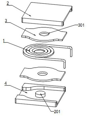
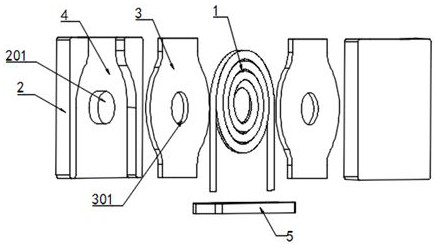
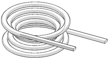
[0056] refer to Figure 1-5 , a power inductor for vehicles with high thermal conductivity, including a magnetic core 2, two magnetic cores 2 are provided, a coil 1 is provided between the two magnetic cores 2, the coil 1 is in a flat spiral structure, and the coil 1 is cabled It is a flat structure, and the inner side of the two magnetic cores 2 that is attached to the external heat sink is embedded with a heat conduction sheet 3. The coil 1 has a small operating current and low power loss. The heat conduction sheet 3 is not installed in the inductor, and the center of the heat conduction sheet 3 A through slot 301 is opened, and the side of the magnetic core 2 close to the coil 1 is provided with a clamping slot 4, and the middle position of the clamping slot 4 is fixedly connected with the magnetic core 2 with a cylindrical limiting column 201, and the limiting column 201 is connected with the magnetic core 2. The heat conducting sheet 3 and the coil 1 are fitted in a slidi...

Embodiment 2

[0072] refer to Figure 1-5 , a power inductor for vehicles with high thermal conductivity, including a magnetic core 2, two magnetic cores 2 are provided, a coil 1 is arranged between the two magnetic cores 2, the coil 1 is in a flat spiral structure, and the coil 1 is cabled It is a flat structure, and the inner side of the two magnetic cores 2 that is attached to the external heat sink is embedded with a heat conduction sheet 3. The coil 1 has a small operating current and low power loss. The heat conduction sheet 3 is not provided in the inductance, and the center of the heat conduction sheet 3 A through slot 301 is opened, and the side of the magnetic core 2 close to the coil 1 is provided with a clamping slot 4, and the middle position of the clamping slot 4 is fixedly connected with the magnetic core 2 with a cylindrical limiting column 201, and the limiting column 201 is connected to the magnetic core 2. The heat conducting sheet 3 and the coil 1 are fitted in a slidin...


PUM


Abstract

The invention discloses a vehicle power inductor with high heat-conducting property, which comprises two magnetic cores, a coil is arranged between the two magnetic cores, the coil is of a flat spiral structure, and a coil cable is of a flat structure. In the invention, the coil is arranged into a flat spiral structure, the upper surface and the lower surface of the coil have a large amount of plane areas, and the coil is matched with a heat conducting sheet on the ground of the magnetic core, so that the heat dissipation capability of the surface of the magnetic core is fully utilized, and the surface of the magnetic core is attached to a radiator of a vehicle body, thereby further improving the heat dissipation performance of a product; the current density of the coil cross section is improved under the condition of certain temperature rise, so that a smaller conductor cross section area is realized, and the product volume is reduced; and when the product adopts a horizontal structure, the gravity center is low, and the stress of a product connecting point is reduced, and when the product adopts a vertical structure, the occupied area for product assembly is small, and the space utilization rate in a vehicle body is increased.

Description

technical field [0001] The invention relates to a vehicle power inductor with high thermal conductivity and an assembly method. Background technique [0002] Due to the long working life of automobile products and harsh working environment (vibration, temperature, humidity, salt spray, altitude, etc.), the safety and reliability requirements are strict; coupled with the informatization and intelligence of automobiles, it is necessary to install in a limited space There are more and more system assemblies in the world, which requires our components to have a lower center of gravity, stronger heat dissipation performance, and smaller installation space. [0003] Existing horizontal power inductors and vertical power inductors generate heat mainly in the wire coil. There is air between the coil and the magnetic core. The thermal conductivity of the air and the plastic base is very poor. Thermal radiation and poor heat dissipation performance; in order to ensure that the workin...

Claims


Application Information

Patent Timeline
IPC IPC(8): H01F27/08H01F27/22H01F27/28H01F27/34H01F41/00
CPCH01F27/08H01F27/22H01F27/2823H01F27/2871H01F27/346H01F41/00
Inventor 李耀光黄敬新
Owner SHENZHEN SUNLORD AUTOMOTIVE ELECTRONICS CO LTD
Learn More