
Display substrate and liquid crystal display panel

A technology for display substrates and display areas, which is applied in the directions of instruments, nonlinear optics, optics, etc., can solve the problem of uneven edge thickness of the alignment film, achieve improved edge thickness unevenness, realize narrow borders or no borders, and uniform edge thickness Effect

Active Publication Date: 2022-05-06
MIANYANG HKC OPTOELECTRONICS TECH CO LTD +1
View PDF5 Cites 0 Cited by
  • Summary
  • Abstract
  • Description
  • Claims
  • Application Information

AI Technical Summary

Problems solved by technology

[0004] The purpose of this application is to provide a display substrate and a liquid crystal display panel, which can improve the problem of uneven edge thickness of the alignment film, and is conducive to the realization of narrow borders or no frame design

Method used


Image

  • Display substrate and liquid crystal display panel
  • Display substrate and liquid crystal display panel
  • Display substrate and liquid crystal display panel

Examples


Embodiment Construction

[0027] Features and exemplary embodiments of various aspects of the present application will be described in detail below. In the following detailed description, numerous specific details are set forth in order to provide a thorough understanding of the application. It will be apparent, however, to one skilled in the art that the present application may be practiced without some of these specific details. The following description of the embodiments is only to provide a better understanding of the present application by showing examples of the present application. In the drawings and the following description, at least some well-known structures and techniques have not been shown in order to avoid unnecessarily obscuring the application; and, for clarity, the dimensions of domain structures may have been exaggerated. Furthermore, the features, structures, or characteristics described hereinafter may be combined in any suitable manner in one or more embodiments.

[0028] fig...


PUM

PropertyMeasurementUnit
diameteraaaaaaaaaa

Abstract

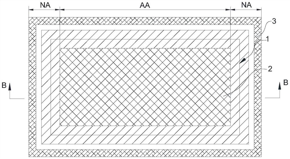
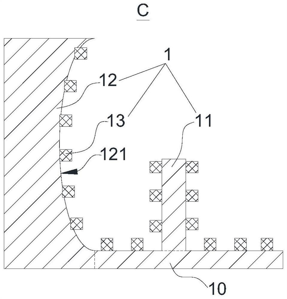
The invention relates to a display substrate and a liquid crystal display panel, the display substrate is provided with a display area and a non-display area located on the periphery of the display area, the display substrate comprises an alignment film located in the display area, frame glue located in the non-display area and a retaining wall located between the alignment film and the frame glue, the retaining wall comprises a supporting part located in the non-display area and a first blocking part and a second blocking part which are formed on the supporting part and arranged at an interval, the second blocking part is located on the side, away from the alignment film, of the first blocking part, the height of the first blocking part is smaller than the film forming thickness of the alignment film, and the height of the second blocking part is larger than the film forming thickness of the alignment film. And a concave arc-shaped surface is formed on one side, facing the first blocking part, of the second blocking part. According to the display substrate, the problem that the edge thickness of the alignment film is not uniform can be solved, and narrow-frame or frameless design can be achieved.

Description

technical field [0001] The present application relates to the field of display technology, in particular to a display substrate and a liquid crystal display panel. Background technique [0002] A liquid crystal display panel (LCD for short) includes an array substrate, a color filter substrate, and a liquid crystal layer located between the array substrate and the color filter substrate. Wherein, an alignment film is respectively formed on the inner side of the array substrate and the color filter substrate to guide the arrangement direction of the liquid crystal molecules. [0003] The alignment film solution is usually evenly coated on the array substrate or color filter substrate by printing plate transfer (APR) or inkjet printing (Inkjet Printing), and then heated and cured, aligned to form a film surface with a channel microstructure. for anchoring liquid crystals. However, in the actual production process, due to the effect of surface tension, the edge of the alignme...

Claims


Application Information

Patent Timeline
Patent Type & Authority Applications(China)
IPC IPC(8): G02F1/1337G02F1/1339
CPCG02F1/13378G02F1/1339
Inventor 李卓安康报虹
Owner MIANYANG HKC OPTOELECTRONICS TECH CO LTD
Learn More