Track cleaning and correcting device
A track and cleaning vehicle technology, applied in the field of track, can solve problems affecting normal use, track with weeds, deformation, etc., to achieve the effect of correcting curvature and reducing potential safety hazards
- Summary
- Abstract
- Description
- Claims
- Application Information
AI Technical Summary
Problems solved by technology
Method used
Image

Examples
Embodiment 1
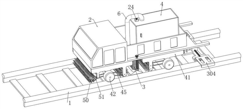
[0042] Embodiment one, such as figure 1 , 2 , shown in 3, 4, a kind of track cleaning and rectifying device, comprises track 1, and described track 1 is exactly existing railway track, and described track 1 is equipped with cleaning car 2 rolling left and right, the middle part of described cleaning car 2 There is a through hole through up and down, and the bottom of the cleaning vehicle 2 is fixedly installed with a dust suction cylinder 3 communicating with the through hole. The dust suction cylinder 3 is an annular threaded pipe structure, which can be stretched up and down. A finishing box 4 is fixedly installed, and the inside of the finishing box 4 is a cavity structure. The upper end of the finishing box 4 is fixedly installed with an upper auger cylinder 5, and a guide is fixedly connected between the upper auger cylinder 5 and the through hole. Pipe 6, the bottom of the finishing box 4 is provided with a square hole up and down, the lower end of the upper auger 5 is ...
Embodiment 2
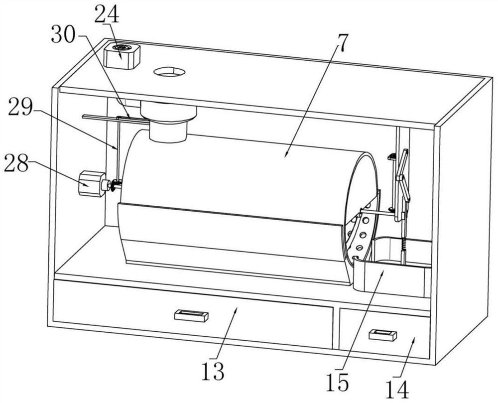
[0044] Embodiment two, on the basis of embodiment one, such as image 3 , 4 , 11, and 14, the bottom of the right side of the finishing box 4 is fixedly installed with an intercepting box 15 located at the outlet on the right side of the separation cylinder 7 and above the right carrying box 14, and the intercepting box 15 and the right carrying box 14 are up and down Through, a pressing plate 16 is installed sliding up and down in the intercepting box 15, and the pressing plate 16 can slide into the right carrying box 14, and a vertical plate 17 above the pressing plate 16 is fixedly installed in the upper end of the finishing box 4 , the left end of the riser 17 is rotatably installed with a lower bevel gear set 18 coaxially fixedly connected with the stirring rod 9, and the lower bevel gear set 18 includes two lower bevel gears, one of which is coaxially fixed on the On the stirring rod 9, another lower bevel gear is rotatably installed on the left side of the vertical pla...
Embodiment 3
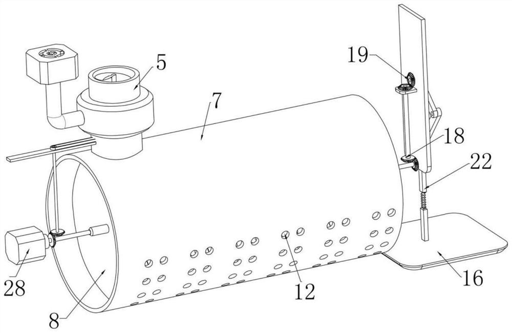
[0046] Embodiment three, on the basis of embodiment one, such as figure 2 , 9 As shown, a plurality of suction holes 22 are provided on the upper auger cylinder 5, and an air intake ring 23 positioned on a plurality of suction holes 22 is fixedly set on the auger cylinder 5, and the finishing box 4 The upper end of the fan 24 is fixedly installed, and the fan 24 is connected to a power supply and a controller, and an air outlet pipe 25 is fixedly installed between the fan 24 and the air inlet ring 23;
[0047] When it is necessary to clean up the rubbish between the two tracks 11, the fan 24 is turned on, and then the fan 24 draws air outwards. At this time, the air in the dust suction tube 3 enters the upper auger tube 5 through the guide tube 6, and then the air passes through. The suction hole 22 enters the air intake ring 23, and then enters the air outlet pipe 25. At the same time, due to the effect of negative pressure, the dust suction tube 3 simultaneously sucks the ...
PUM
 Abstract
Description
Claims
Application Information
 - R&D
- Intellectual Property
- Life Sciences
- Materials
- Tech Scout
- Unparalleled Data Quality
- Higher Quality Content
- 60% Fewer Hallucinations
Browse by: Latest US Patents, China's latest patents, Technical Efficacy Thesaurus, Application Domain, Technology Topic, Popular Technical Reports.
© 2025 PatSnap. All rights reserved.Legal|Privacy policy|Modern Slavery Act Transparency Statement|Sitemap|About US| Contact US: help@patsnap.com