
Electroplating liquid anti-leakage carrier and anti-leakage treatment process thereof

A treatment process and electroplating solution technology, applied in the direction of plating tanks, electrolytic components, electrolytic processes, etc., can solve problems such as ignoring root causes, plant growth hazards, treating symptoms but not root causes, and achieving easy system construction, strong mobility, and reduced damage effect

Pending Publication Date: 2022-05-06
深圳市虹喜科技发展有限公司
View PDF3 Cites 0 Cited by
  • Summary
  • Abstract
  • Description
  • Claims
  • Application Information

AI Technical Summary

Problems solved by technology

These exhaust gases are harmful to the human respiratory tract, eyes, and skin. Experimental personnel or electroplating and electroplating workers have been exposed to such exhaust gases for a long time, causing great harm to the body, and even some sulfur dioxide and nitrogen oxides emitted in the air are harmful to plants. Harmful to growth, even kills plants
[0003] Therefore, exhaust gas treatment is an urgent problem to be solved at home and abroad. Nowadays, exhaust gas is often treated by installing a suction fan on the top of the workshop or exhaust gas generating facility, blowing the exhaust gas into the purification tower, and then passing through a series of photocatalytic and plasma treatments. , chimney high-altitude emissions, etc., but this method only pays attention to the protection of the entire ecosystem, and indeed ignores the root cause of people-oriented problems. For example, the existing reaction tanks adopt fixed positions and fixed forms, and the electroplating solution needs to be replaced frequently And clean the reaction tank, the gas deposited at the bottom of the reaction tank will accumulate and cause harm to the human body, and many workshops only use regular testing to see if the concentration of exhaust gas in the workshop meets the standard, but this is undoubtedly a temporary solution, not a permanent cure

Method used


Image

  • Electroplating liquid anti-leakage carrier and anti-leakage treatment process thereof
  • Electroplating liquid anti-leakage carrier and anti-leakage treatment process thereof
  • Electroplating liquid anti-leakage carrier and anti-leakage treatment process thereof

Examples


Embodiment 1

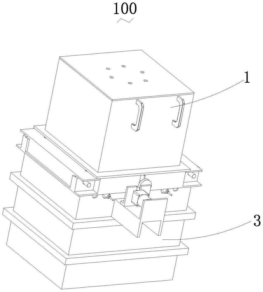
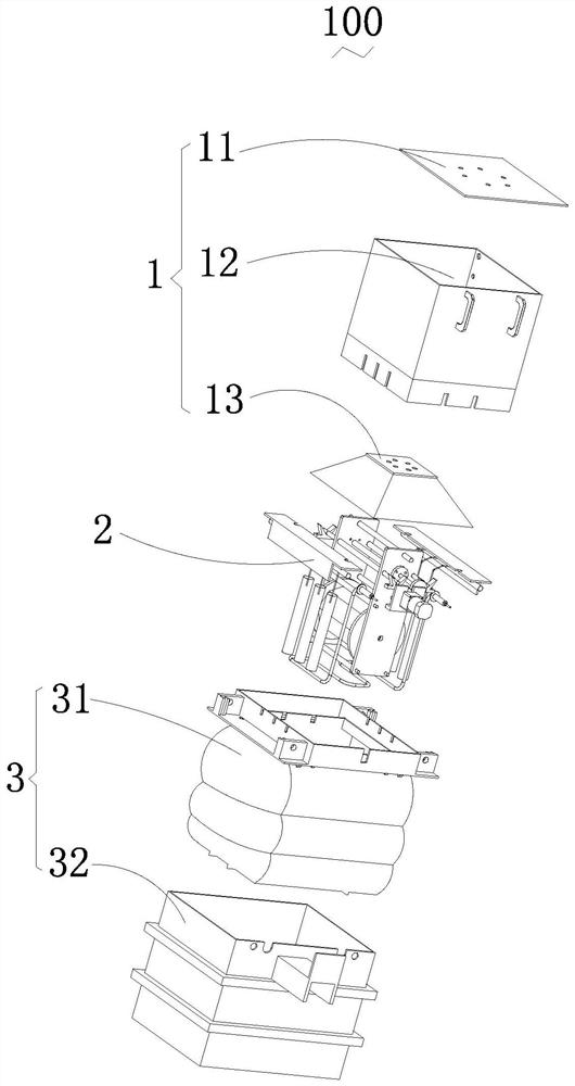
[0042] Embodiment 1 provided by the present invention mainly provides the anti-leakage carrier for electroplating solution, as well as the included mechanisms and their positional relationship and functions:

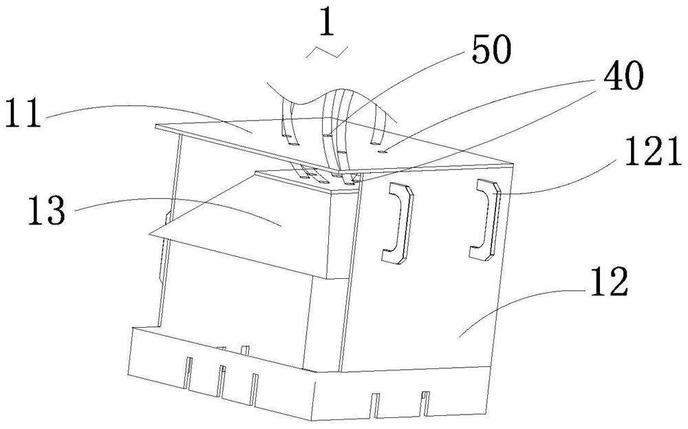
[0043] The electroplating solution leakage prevention carrier 100 includes an upper chamber cover 1 and a lower chamber groove 3, the upper chamber cover 1 and the lower chamber groove 3 can be covered to form a space, the space includes an electroplating mechanism 2, and the The anti-leakage carrier of the electroplating solution is also provided with a controller (not shown in the figure). The controller can be an industrial computer or a PLC, which can be debugged through an external connection to a host computer. All mechanical actions described below in the present invention are performed through the controller Execution, since the controller is a common technical feature for those skilled in the art, the present invention does not specifically describe the controlle...

Embodiment 2

[0060] In order to better solve the above problems, Embodiment 2 provided by the present invention mainly provides the anti-leakage treatment process of the electroplating solution leakage prevention carrier; based on the structural characteristics and connection relationship of the electroplating solution leakage prevention carrier described in Embodiment 1 Above, the anti-leakage treatment process of the electroplating solution anti-leakage carrier includes the following steps:

[0061] Step S1: Provide an upper chamber cover and a lower chamber groove, the upper chamber cover and the lower chamber groove can be covered to form a space, provide an air bag and set it on the upper chamber cover and the lower chamber gap in the groove;

[0062] Step S2: During the working state, use the space as the electroplating reaction tank and input the electroplating solution, inflate and expand the air bag to close the gap between the upper chamber cover and the lower chamber tank, and sim...


PUM


Abstract

The invention relates to an electroplating liquid leakage prevention carrier which comprises an upper containing cavity cover and a lower containing cavity groove, the upper containing cavity cover and the lower containing cavity groove are matched with each other to be covered, and an air bag is arranged at the gap between the upper containing cavity cover and the lower containing cavity groove. Air guide holes and liquid guide holes are formed in the top and the bottom of the electroplating liquid leakage prevention carrier, at least one liquid guide hole is externally connected with electroplating liquid supply equipment, at least one air guide hole is externally connected with nitrogen supply equipment, and at least one air guide hole is externally connected with a vacuum pump. At least one air guide hole is formed in the bottom of the electroplating liquid leakage prevention carrier and externally connected with an air pump to inflate and deflate the air bag, and at least one liquid guide hole is communicated with the interior of the lower containing cavity groove so that the electroplating liquid in the lower containing cavity groove can be emptied.

Description

【Technical field】 [0001] The invention relates to the technical field of electroplating, in particular to an anti-leakage carrier for electroplating solution and an anti-leakage treatment process thereof. 【Background technique】 [0002] Electroplating is often used in the electronics and metal industries. Whether it is the manufacturer of the plating solution or the company using the plating solution, as far as the existing electroplating process is concerned, a large amount of waste gas will inevitably be generated during the experimental process or the electroplating process. The waste gas is mainly organic Waste gas, acid and alkali waste gas, chromic acid mist, metal dust and various waste gases emitted by heating various electroplating baths, such as cyanide-containing waste gas, ammonia-containing waste gas, etc. These exhaust gases are harmful to the human respiratory tract, eyes, and skin. Experimental personnel or electroplating and electroplating workers have been ...

Claims


Application Information

Patent Timeline
Patent Type & Authority Applications(China)
IPC IPC(8): C25D17/00C25D17/02C25D21/02C25D21/04C25D21/08C25D21/10
CPCC25D17/00C25D17/02C25D17/004C25D21/04C25D21/02C25D21/08C25D21/10
Inventor 吴旭明蔡良胜陈阳蔡绪开
Owner 深圳市虹喜科技发展有限公司
Learn More