Rapid clamping structure and mechanical clamping device

A clamping device and clamping technology, applied in positioning devices, metal processing machinery parts, clamping, etc., can solve the problems of low machine utilization rate, long downtime, long correction time, etc., and improve machine utilization The effect of high efficiency, reduced downtime, and precise positioning of assembly

Pending Publication Date: 2022-05-06
厦门宏发精密机械有限公司
View PDF0 Cites 0 Cited by
  • Summary
  • Abstract
  • Description
  • Claims
  • Application Information

AI Technical Summary

Problems solved by technology

For example, in the slow wire process in the prior art, the processing fixture (vice) used in the original processing needs to be calibrated individually in the machine tool, and the stoppage of the parts to find the alignment and waste of invalid actions lead to long correction time, which in turn leads to long downtime. Resulting in low machine utilization
With the increase of tasks and the accumulation of parts, the delivery time lags and the cost rises

Method used


Image

  • Rapid clamping structure and mechanical clamping device
  • Rapid clamping structure and mechanical clamping device
  • Rapid clamping structure and mechanical clamping device

Examples


Embodiment 1

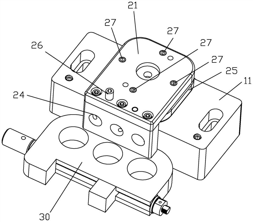
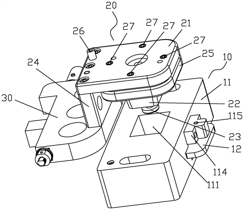
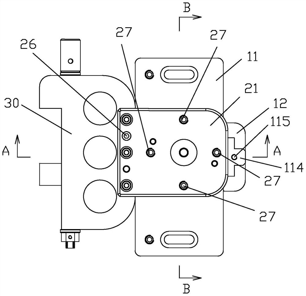
[0031] This embodiment provides a quick clamping structure, such as Figure 1 to Figure 10 As shown, it includes a fixing device 10 and an exchange device 20. The fixing device 10 includes a fixing base 11 and a clamping plate 12. The fixing base 11 is provided with a frustum-shaped positioning channel 111 that is wide at the top and narrow at the bottom. The clamping plate 12 is movably arranged at the bottom of the positioning slot 111 , and has a large opening 121 and a small opening 122 connected thereto. The big mouth 121 is used for giving way, and the small mouth 122 is used for clamping.

[0032] More specifically, the fixed base 11 has a slot 113 arranged horizontally, and the slot 113 is located at the bottom of the positioning channel 111 ;

[0033] The exchange device 20 includes a fixed plate 21 and a positioning block 22 and a connecting block 24 respectively fixed on the fixed plate 21, and the connecting block 24 is used to connect a working fixture 30 (such a...

Embodiment 2

[0043] This embodiment provides a mechanical clamping device, including a processing machine tool, a fixing device, an exchange device for assembling on the fixing device, and a work fixture assembled on the exchange device; the number of the fixing devices is at least two , which is used to switch between the external preset position and the internal position of the processing machine tool; in this way, it is possible to assemble the work fixture at the external preset position first, and then transfer it to the machine tool (that is, the internal position) for processing Operation, can avoid long downtime to install and replace the operation fixture.

[0044] Specifically, the installation structure of the fixing device and the interchange device is the same as the quick clamping structure in Embodiment 1, specifically: refer to Figure 1 to Figure 10 As shown, the fixing device 10 includes a fixing base 11 and a clamping plate 12. The fixing base 11 is provided with a trunc...


PUM


Abstract

The invention provides a quick clamping structure and a mechanical clamping device.The quick clamping structure comprises a fixing device and an interchanging device, the fixing device comprises a fixing base and a clamping plate, the fixing base is provided with a frustum-shaped positioning through groove with the wide upper portion and the narrow lower portion, and the clamping plate is movably arranged at the bottom of the positioning through groove in a drawable mode; the large opening and the small opening are communicated with each other; the interchanging device comprises a fixing plate, a positioning block and a connecting block, the positioning block and the connecting block are fixed to the fixing plate, the connecting block is used for being connected with an operation jig, the positioning block is of a frustum-shaped structure matched with the positioning through groove in appearance, and a clamping head is arranged at the bottom of the positioning block. The interchanging device is positioned by inserting the positioning block into the positioning through groove of the fixing base, the clamping head penetrates through the large opening of the clamping plate, and the clamping plate is pulled to enable the small opening to be connected with the clamping head in a clamping mode so as to achieve fixation of the fixing device and the interchanging device. And the operation jig can be quickly and accurately clamped.

Description

technical field [0001] The invention relates to the field of machining, in particular to a quick clamping structure and a mechanical clamping device. Background technique [0002] Machining refers to the process of changing the shape or performance of a workpiece through a mechanical device. For example, in the slow wire process in the prior art, the processing fixture (vice) used in the original processing needs to be calibrated individually in the machine tool, and the stoppage of the parts to find the alignment and waste of invalid actions lead to long correction time, which in turn leads to long downtime. As a result, the machine utilization rate is not high. As the workload increases and parts accumulate, delivery delays and costs increase. Contents of the invention [0003] For this reason, the present invention provides a quick clamping structure and a mechanical clamping device, which can quickly and accurately clamp the jig and effectively improve the utilizatio...

Claims


Application Information

Patent Timeline
Patent Type & Authority Applications(China)
IPC IPC(8): B23Q3/00
CPCB23Q3/00
Inventor 喻永群杨思良
Owner 厦门宏发精密机械有限公司
Why Eureka
Try Eureka