Cutting device and method for machining iron art guardrail accessories

A cutting device and guardrail technology, applied in metal processing, positioning devices, metal processing equipment, etc., can solve problems such as low efficiency and operator injury, and achieve the effects of high reliability, avoidance of transportation, and strong practicability

Pending Publication Date: 2022-05-06
徐州科美瑞门窗科技有限公司
View PDF5 Cites 2 Cited by
  • Summary
  • Abstract
  • Description
  • Claims
  • Application Information

AI Technical Summary

Problems solved by technology

[0003] Before using the existing railings, most of the railings need to be cut according to the required environment to cut the railings into a suitable size. However, the current cutting device needs to manually push and fix the wrought iron railings when cutting the railing accessories. The need for different lengths and sizes, this method is not only inefficient, but also easy to cause injury to the operator during the cutting process, therefore, further improvement is required

Method used


Image

  • Cutting device and method for machining iron art guardrail accessories
  • Cutting device and method for machining iron art guardrail accessories
  • Cutting device and method for machining iron art guardrail accessories

Examples


Embodiment 1

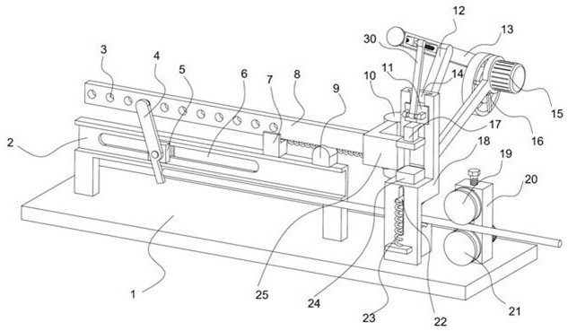
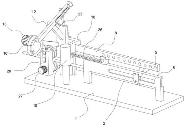
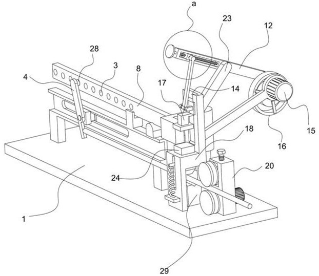
[0035] refer to Figure 1-7 , in an embodiment of the present invention, a cutting device for processing wrought iron guardrail accessories, including a fixed base 1, one end of the upper side of the fixed base 1 is fixedly mounted with a guide rail plate 2, and a guide groove 6 is arranged inside the guide rail plate 2, and the inside of the guide groove 6 The guide block 5 is detachably installed. In this embodiment, bolts can be installed on the upper and lower sides of the back of the guide block 5, thereby realizing the retention of the guide block 5 at a specific position inside the guide groove 6, and finally adjusting the length of the cut wrought iron guardrail. Adjust to ensure the scope of application of the entire cutting device. The guide block 5 is rotated and installed with the interference rod 4. A horizontal translation mechanism is installed on the top of the interference rod 4. The movement direction of the translation mechanism contacts the compensation bloc...

Embodiment 2

[0049] In another embodiment of the present invention, the difference between this embodiment and the above-mentioned embodiment is that the power mechanism includes a power frame 13, and the power frame 13 is installed on the cutting frame 18 through the connecting frame 12. One side of the power frame 13 slides and installs a power block 36, the power block 36 is hinged on the lifting block 11 by a power rod 30, and a lead screw 37 is installed on the power block 36 through a threaded structure, so that the rotary motion of the lead screw 37 is converted into The linear movement of the power block 36 inside the power frame 13, the screw 37 passes through the power frame 13 and is connected with a handle 35, which facilitates the staff to effectively drive the screw 37 to rotate, and the power frame 13 is far away from the power block 36 A power column 32 is fixedly installed on one side, and a power disc 16 is installed on the power column 32. A power motor 15 is connected to...


PUM


Abstract

The invention relates to the technical field of guardrail machining equipment, and discloses a cutting device for iron art guardrail accessory machining, which comprises a fixed base, a guide rail plate is fixedly mounted at one end of the upper side of the fixed base, a guide groove is formed in the guide rail plate, a guide block is detachably mounted in the guide groove, and an abutting rod is rotatably mounted on the guide block. A horizontally-moving translation mechanism is mounted at the top of the abutting rod, a compensation block is in contact with the translation mechanism in the moving direction, a rotating cylinder rotationally arranged on the fixed base is fixed to the compensation block, a feeding mechanism is mounted on the side, away from the guide rail plate, of the upper side of the fixed base, and a cutting frame mounted on the fixed base is arranged in the feeding direction of the feeding mechanism. A power mechanism used for driving the lower pressing block to reciprocate is further installed on the upper side of the cutting frame. The invention further discloses a cutting method. According to the iron art guardrail accessory cutting device, the cutting requirement for iron art guardrail accessories of different lengths is met, meanwhile, effective depth cutting adjustment can be conducted on an iron art guardrail, and the cutting efficiency is further improved.

Description

technical field [0001] The invention relates to the technical field of guardrail processing equipment, in particular to a cutting device and method for processing wrought iron guardrail accessories. Background technique [0002] The application of iron art originated from Europe and has a long history. With the continuous improvement of material and cultural levels, people's production and quality of life are constantly beautifying. Iron art products are increasingly popular due to their unique artistic charm, environmental protection and safety features It is generally accepted and loved by people, especially in recent years, with the emphasis on environmental protection and permeability, a large number of iron guardrails have been used in home decoration. [0003] Before using the existing railings, most of the railings need to be cut according to the required environment to cut the railings into a suitable size. However, the current cutting device needs to manually push a...

Claims


Application Information

Patent Timeline
Patent Type & Authority Applications(China)
IPC IPC(8): B23D79/00B23Q7/00B23Q3/00
CPCB23D79/00B23Q7/00B23Q3/00
Inventor 张建王山王丹丹
Owner 徐州科美瑞门窗科技有限公司
Why Eureka
Try Eureka