
System and method for cooling slurry

A mud and cooling cavity technology, applied in the field of oil and gas well drilling, can solve the problems of large site conditions and environmental impact, affecting the normal use of measuring instruments, reducing the service life of downhole tools, etc., to achieve improved bottom temperature, good application effect and economical benefits, effects of avoiding adverse effects

Pending Publication Date: 2022-05-03
CHINA PETROLEUM & CHEM CORP +3
View PDF0 Cites 0 Cited by
  • Summary
  • Abstract
  • Description
  • Claims
  • Application Information

AI Technical Summary

Problems solved by technology

The substantial temperature rise of the mud not only affects the performance of the mud, but also reduces the service life of downhole tools and affects the normal use of measuring instruments. On the other hand, the high temperature of the drilling mud returned to the ground also poses a threat to the safety of drilling operations.
At present, in the drilling construction operation, the means of cooling the mud is usually to extend the path of the mud tank during construction, so that the mud is naturally cooled in the circulation. This method is greatly affected by the site conditions and the environment, and the cooling effect is poor.

Method used


Image

  • System and method for cooling slurry
  • System and method for cooling slurry
  • System and method for cooling slurry

Examples


Embodiment 1

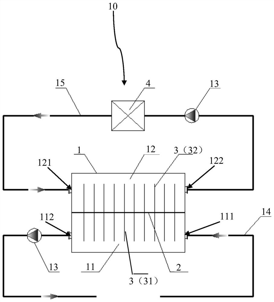
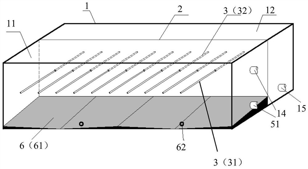
[0037] Such as figure 1 As shown, the system 10 for mud cooling according to the embodiment of the present invention includes a mud cooling tank 1 . Wherein, the mud cooling tank 1 is provided with a partition 2, and the partition 2 is provided with evenly spaced heat pipes 3, and the partition 2 separates the mud cooling tank 1 into a cooling chamber 11 and a heating chamber 12, and the evaporation section 31 of the heat pipe 3 Located in the cooling chamber 11 , the condensation section 32 of the heat pipe 3 is located in the heating chamber 12 . One side of the cooling chamber 11 is provided with a mud inlet 111 for mud to flow in, and the other side of the cooling chamber 11 is provided with a mud outlet 112 for mud to flow out. The same side of the heating chamber 12 as the mud outlet 112 is provided with a cooling water inlet 121 for cooling water to flow in, and the other side of the heating chamber 12 is provided with a cooling water outlet 122 for cooling water to fl...

Embodiment 2

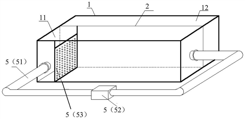
[0047] The method for cooling mud according to the embodiment of the present invention is implemented by using the above-mentioned system 10, and specifically includes the following steps: S01. Install the above-mentioned system. S02. Send the high-temperature mud into the cooling chamber through the mud inlet, contact the evaporation section of the heat pipe, and transfer heat to the low-temperature cooling water flowing from the cooling water inlet into the heating chamber and contacting the condensation section of the heat pipe for cooling. The cooled mud passes through The mud flows out from the outlet and enters the drilling fluid circulation system at the well site. S03. The heated cooling water flows out through the cooling water outlet, and is transported to the cooling device by the cooling water pipeline of the circulating pump well. After evaporative cooling is completed, it flows back into the heating chamber of the mud cooling tank. S04, start the self-circulation...


PUM


Abstract

The invention provides a system and method for cooling slurry. The system comprises a slurry cooling tank, a partition plate is arranged in the slurry cooling tank, a heat pipe is arranged on the partition plate, the slurry cooling tank is divided into a cooling cavity and a heating cavity by the partition plate, an evaporation section of the heat pipe is located in the cooling cavity, and a condensation section of the heat pipe is located in the heating cavity. One side of the cooling cavity is provided with a slurry inlet facilitating inflow of slurry, and the other side of the cooling cavity is provided with a slurry outlet facilitating outflow of the slurry. A cooling water inlet convenient for cooling water to flow in is formed in one side, which is the same as the slurry outlet, of the heating cavity, and a cooling water outlet convenient for cooling water to flow out is formed in the other side of the heating cavity. The system and the method provided by the invention are flexibly matched with a well site drilling fluid circulating system for use in a modular transportation and assembly mode, and achieve the effect of continuously and effectively reducing the temperature of mud entering a well through size operation, so that the high temperature at the bottom of the well is improved, the stability of a borehole is improved, and the adverse effect of the high temperature at the bottom of the well on an underground measuring tool is avoided.

Description

technical field [0001] The invention belongs to the technical field of oil and gas well drilling, and in particular relates to a cooling system and method for mud. Background technique [0002] With the development of oil drilling technology, deep well, ultra-deep well, and high temperature and high pressure well technology have become an important development trend in the oil drilling industry. However, due to the increase in depth, new problems are also faced in the drilling process. According to the actual measurement, when the well depth exceeds 7000m, the temperature at the bottom of the well can reach 200°C. At the same time, the drilling tool cuts rocks, the friction between the drill pipe and the well wall will also generate a lot of heat, and this heat will be continuously transferred to the mud, making the mud temperature in the well too high. high. The substantial temperature rise of the mud not only affects the performance of the mud, but also reduces the servic...

Claims


Application Information

Patent Timeline
IPC IPC(8): F28D15/02E21B21/06
CPCF28D15/0266E21B21/06
Inventor 黄松伟张金法李文伟胡群爱毕文明赵聪郑雨蒙梁晓阳赵向阳
Owner CHINA PETROLEUM & CHEM CORP
Learn More