
Drill floor pipe grabbing manipulator with self-adaptive size

An adaptive and manipulator technology, which is applied in the direction of manipulators, program control manipulators, manufacturing tools, etc., can solve the problems of small opening and closing of fingers and affect the efficiency of automatic pipe arrangement, and achieve the effect of small flight attendant, compact structure and large opening and closing.

Pending Publication Date: 2022-05-03
CHINA PETROLEUM & CHEM CORP +1
View PDF2 Cites 0 Cited by
  • Summary
  • Abstract
  • Description
  • Claims
  • Application Information

AI Technical Summary

Problems solved by technology

[0005] The main purpose of the present invention is to provide a size-adaptive drill floor pipe grasping manipulator, which solves the problem that the existing drill floor manipulator mainly uses ring gripping, and the opening and closing degree of the fingers is small. It is necessary to replace the manipulator, which seriously affects the efficiency of automatic pipe arrangement

Method used


Image

  • Drill floor pipe grabbing manipulator with self-adaptive size
  • Drill floor pipe grabbing manipulator with self-adaptive size
  • Drill floor pipe grabbing manipulator with self-adaptive size

Examples


Embodiment 1

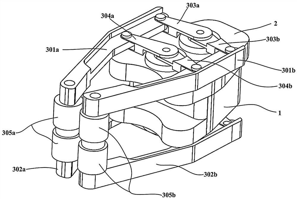
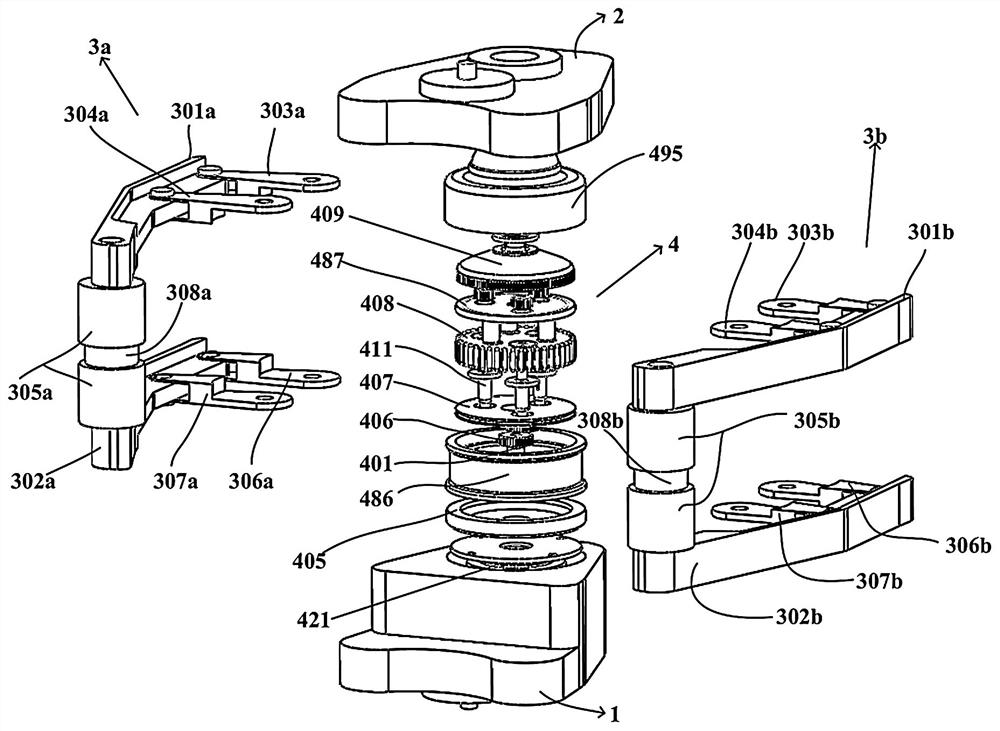
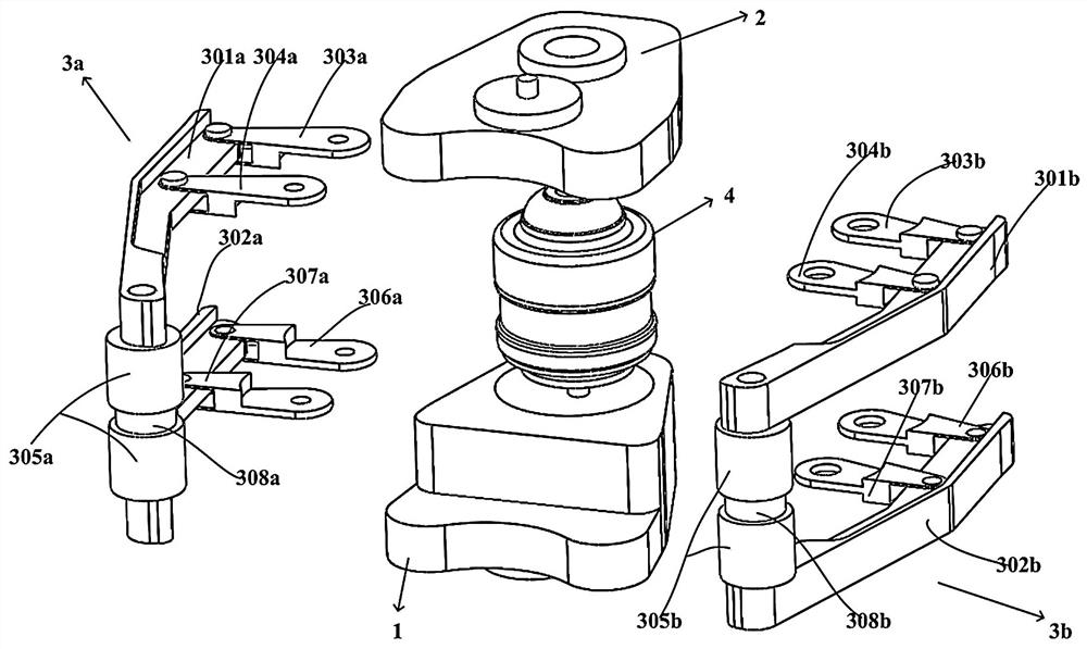
[0037] Such as Figure 1-8 As shown, a size-adaptive drill floor pipe grasping manipulator includes a base 1, and a compound gear train reducer 4 is arranged inside the base 1, and the compound gear train reducer 4 drives two output outer shafts 412 and output inner shafts with opposite directions of rotation. Shaft 414, the top of the base 1 is connected with the top cover 2, the two sides of the base 1 are provided with a clamping mechanism, the middle part of the clamping mechanism on one side is hinged with the top cover 2 through a connecting rod, and the connecting rods at the tail ends of the clamping mechanism on both sides are respectively connected with two An output outer shaft 412 and an output inner shaft 414 of opposite rotation are connected. The output mechanism is connected with the composite gear train reducer 4, and the composite gear train reducer 4 drives the output outer shaft 412 and the output inner shaft 414 to rotate in opposite directions. In the cl...

Embodiment 2

[0049] Further illustrate in conjunction with embodiment 1, as Figure 1-8 As shown, a size-adaptive drill floor pipe grasping manipulator of the present invention includes a base 1, a top cover 2, a clamping mechanism 3 (a-b), a compound gear train reducer 4; the compound gear train reducer includes a planetary gear transmission mechanism, Cycloid planetary reduction mechanism, harmonic gear reduction mechanism.

[0050] Among them, the clamping mechanism includes fingers 301 (a-b) and 302 (a-b), connecting rods 303 (a-b), 304 (a-b), rollers 305 (a-b), and roller shafts 308 (a-b); four fingers in pairs, Among them, 301a and 302a are a group, and 301b and 302b are a group, which are respectively installed on both sides of the base 1 and the top cover 2; the upper right finger 301a passes through the upper right tail connecting rod 303a and the output of the compound gear train reducer 4 The inner shaft 414 is connected, and the finger 301a is connected to the top cover 2 by u...


PUM


Abstract

The invention provides a size self-adaptive drill floor pipe grabbing manipulator which is characterized in that a composite gear train speed reducer is arranged in a base and drives an output outer shaft and an output inner shaft which are opposite in rotation direction, clamping mechanisms are arranged on the two sides of the base, and the middle of the clamping mechanism on one side is hinged to a top cover through a connecting rod; the connecting rods at the tail ends of the clamping mechanisms on the two sides are connected with an output outer shaft and an output inner shaft which are opposite in rotating direction respectively, and the two connecting rods, the clamping mechanisms and the base form a parallelogram mechanism. The pipe grabbing manipulator can be applied to an automatic pipe arranging system of a drill floor, and pipe columns with different pipe diameters can be grabbed in a self-adaptive mode. System power is transmitted to the composite gear train speed reducer through the input shaft, the power is output from two coaxial output shafts under the action of a cycloidal-pin gear speed reducing mechanism and a harmonic gear speed reducing mechanism in the composite gear train speed reducer, and the rotation directions of the two output shafts are opposite. The tail ends of two fingers in the clamping mechanism are connected with the two output shafts correspondingly to achieve opening and closing of the fingers.

Description

technical field [0001] The invention relates to the field of pipe grasping manipulators, in particular to a dimension adaptive drill floor pipe grasping manipulator. Background technique [0002] In the process of oil drilling, tripping, tripping in and discharge of drilling tools is a production activity with a single manual action and high repetition. With the development of automatic drilling rig technology, the mechanical arm has also become an important part of the automatic pipe arrangement device. It can not only greatly improve the production efficiency while reducing the work intensity of oil workers, but also reduce the damage caused by manual operation errors. Accident risk rate. As an important part of the manipulator, the manipulator can assist the manipulator to complete a series of operations such as picking up, carrying, flipping, and squeezing the target object. The existing drill floor manipulators in China mainly use the ring grip, and the opening and cl...

Claims


Application Information

Patent Timeline
Patent Type & Authority Applications(China)
IPC IPC(8): B25J9/08B25J19/00
CPCB25J9/08B25J19/00
Inventor 陈克应左远涛周四龙宋一丁国栋邹康罗天保夏颖韬
Owner CHINA PETROLEUM & CHEM CORP
Learn More