Mechanical multi-turn encoder for joint of foot-type robot

A robot joint and encoder technology, applied in metal processing equipment, metal processing, manufacturing tools, etc., can solve the problems of reducing the cost and volume of the encoder, reducing the volume and cost of the encoder, and difficult installation

Pending Publication Date: 2022-05-03
南京蔚蓝智能科技有限公司
View PDF0 Cites 0 Cited by
  • Summary
  • Abstract
  • Description
  • Claims
  • Application Information

AI Technical Summary

Problems solved by technology

[0007] The mechanical multi-turn encoder has the following advantages: (1) The structure is simple, and only one-stage transmission of two gears is needed to realize multi-turn counting, which replaces the traditional multi-stage reduction gear scheme and effectively simplifies the mechanical multi-turn absolute The structure of the value encoder overcomes the shortcomings of the traditional mechanical multi-turn encoder with complex structure and difficult installation; (2) The gear part of the mechanical multi-turn encoder is designed together with the motor structure, which saves the intermediate transmission structure and greatly The volume and cost of the encoder are reduced; (3) the magnetic induction chip of the mechanical multi-turn encoder is integrated on the motor driver board, and the controller in the motor driver circuit can directly read the position data in the magnetic induction chip, eliminating the need for Encoder chip dedicated circuit board and connecting cables further reduce the cost and volume of the encoder

Method used


Image

  • Mechanical multi-turn encoder for joint of foot-type robot
  • Mechanical multi-turn encoder for joint of foot-type robot
  • Mechanical multi-turn encoder for joint of foot-type robot

Examples


Embodiment Construction

[0020] The technical means adopted by the present invention to achieve the intended invention purpose are further described below in conjunction with the drawings and preferred embodiments of the present invention.

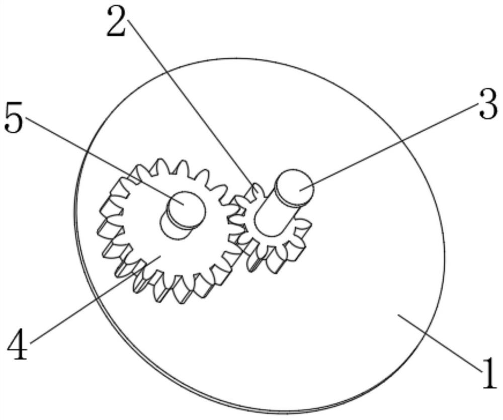
[0021] Please refer to figure 1 as shown, figure 1 It is a schematic diagram of the gears of the mechanical multi-turn encoder of the present invention. This mechanical multi-turn encoder comprises driving gear 2, master magnet 3, driven gear 4, slave magnet 5, master magnetic induction chip and slave magnetic induction chip (main magnetic induction chip and slave magnetic induction chip are not in figure 1 shown in ). Wherein, the driving gear 2 is coaxially connected with the motor shaft, and the main magnet 3 is installed on the motor shaft end, coaxially arranged with the driving gear 2, and the driving gear 2 and the main magnet 3 rotate together with the motor shaft. The driven gear 4 is installed on the motor rear end cover 1, the slave magnet 5 is coaxi...


PUM


Abstract

The invention provides a mechanical multi-turn encoder for a foot type robot joint, the mechanical multi-turn encoder comprises a driving gear, a master magnet, a driven gear, a slave magnet, a master magnetic induction chip and a slave magnetic induction chip, the driving gear is coaxially connected with a motor shaft, the master magnet is installed at the end of the motor shaft and is coaxially arranged with the driving gear, and the slave magnet is installed at the end of the motor shaft and is coaxially arranged with the driven gear. The driving gear and the main magnet rotate together with the motor shaft; the driven gear is installed on the motor rear end cover, and the driven magnet and the driven gear are coaxially arranged. The driving gear is meshed with the driven gear and drives the driven gear and the driven magnet to rotate; the master magnetic induction chip and the slave magnetic induction chip are connected with a controller in the motor driver, and the master magnetic induction chip and the slave magnetic induction chip are arranged right opposite to the master magnet and the slave magnet respectively. The gear of the encoder is directly installed on the motor, and the magnetic induction chip is integrated on the motor driving board, so that the cost and the size of the encoder are greatly reduced.

Description

technical field [0001] The invention relates to the field of legged robots, in particular to a mechanical multi-turn encoder for the joints of a legged robot. Background technique [0002] Footed robot is a particularly popular research field in recent years, because footed robot has good environmental adaptability, it can move in complex environments such as grass, rugged mountains, potholes, etc., and can complete rescue and exploration tasks in dangerous environments . The joints of a legged robot are its core components, and the performance of the joints will directly affect the power and control performance of the legged robot. [0003] The joint of the legged robot is a highly integrated module, including motors, reducers, drives, encoders, etc. Among them, the encoder is used to obtain the position information of the joint and is an indispensable sensor for robot control. At present, the encoder scheme of the legged robot joint is generally to install a multi-turn ...

Claims


Application Information

Patent Timeline
Patent Type & Authority Applications(China)
IPC IPC(8): B23P19/02B23P19/00
CPCB23P19/02B23P19/00
Inventor 不公告发明人
Owner 南京蔚蓝智能科技有限公司
Why Eureka
Try Eureka