Radio frequency antenna manufacturing method and radio frequency antenna

A technology of radio frequency antenna and manufacturing method, which is applied in the field of antenna manufacturing, and can solve the problems that solder joint substrates are easily welded through, high defect rate, and low manufacturing efficiency, etc.

Active Publication Date: 2022-07-26
SHENZHEN YUANMINGJIE TECH
View PDF6 Cites 0 Cited by
  • Summary
  • Abstract
  • Description
  • Claims
  • Application Information

AI Technical Summary

Problems solved by technology

[0007] The main purpose of the present invention is to provide a radio frequency antenna manufacturing method and radio frequency antenna, aiming to solve the problem that the welding process of the prior art adopts the welding process to manufacture the smart card, which causes the base material to be easily welded through due to the large number of solder joints, thereby resulting in production efficiency. Technical issues with low and high defect rates

Method used


Image

  • Radio frequency antenna manufacturing method and radio frequency antenna
  • Radio frequency antenna manufacturing method and radio frequency antenna
  • Radio frequency antenna manufacturing method and radio frequency antenna

Examples


Embodiment Construction

[0047] The technical solutions in the embodiments of the present invention will be clearly and completely described below with reference to the accompanying drawings in the embodiments of the present invention. Obviously, the described embodiments are only a part of the embodiments of the present invention, but not all of the embodiments. Based on the embodiments of the present invention, all other embodiments obtained by those of ordinary skill in the art without creative efforts shall fall within the protection scope of the present invention.

[0048] It should be noted that all directional indications (such as up, down, left, right, front, back, etc.) in the embodiments of the present invention are only used to explain the relationship between various components under a certain posture (as shown in the accompanying drawings). The relative positional relationship, the movement situation, etc., if the specific posture changes, the directional indication also changes accordingl...


PUM


Abstract

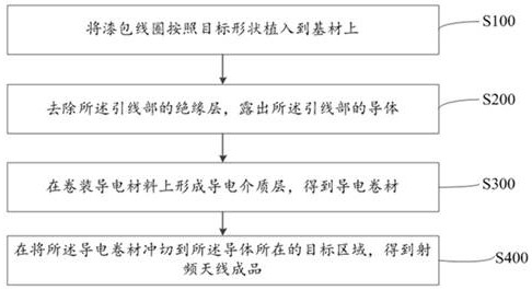
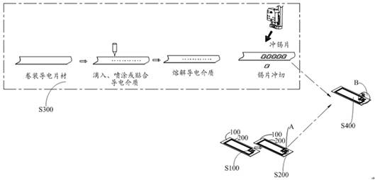
The invention relates to the technical field of antenna manufacturing, in particular to a method for manufacturing a radio frequency antenna and a radio frequency antenna. By implanting an enameled coil on a substrate according to a target shape, and then removing the insulating layer of the lead part by milling or grinding, the lead wire is exposed. Then drop a conductive medium onto the packaged conductive material to form a conductive coil, and press the conductive coil to the target area where the conductor of the lead part is located to form a structure that is electrically connected to the conductor, and let the conductor and the conductive medium The finished product of the radio frequency antenna with the layers integrally formed and electrically connected, so that the present invention no longer needs to use the touch welding method to remove the insulating layer on the enameled coil in the process of making the radio frequency antenna as in the prior art, which solves the problem of the prior art. When the insulating layer on the enameled coil is removed by the butt welding method, the base material is welded through due to the large number of solder joints, resulting in low efficiency and technical defects affecting the yield.

Description

technical field [0001] The invention relates to the technical field of antenna manufacturing, in particular to a manufacturing method of a radio frequency antenna and a radio frequency antenna. Background technique [0002] At present, different types of smart cards with different functions are widely used in various fields. [0003] The antenna is the main structure of the material in the smart card. [0004] In the prior art, the production process of the smart card is as follows: [0005] Carry out punching of base material positioning holes and conductive sheet hole avoidance holes → place the non-metallic base material on the working table of the ultrasonic wire embedding machine, and use the above positioning holes to position the material, and at the same time determine the position of the embedding wire and the avoidance of the wire head crossing. Empty hole position→Attach tape on the position where the buried non-metallic substrate crosses the empty hole of the c...

Claims


Application Information

Patent Timeline
Patent Type & Authority Patents(China)
IPC IPC(8): H01Q1/36H01Q1/22H01Q1/50
CPCH01Q1/36H01Q1/50H01Q1/22
Inventor 黎理彬邹大卡黎理明黎理杰
Owner SHENZHEN YUANMINGJIE TECH
Why Eureka
Try Eureka