High-power power transformer

A high-power power supply and transformer technology, applied in transformer/inductor cooling, transformer/reactor installation/support/suspension, transformer/inductor coil/winding/connection, etc., can solve the problem of no auxiliary stability and damping, utilization Low, slow heat dissipation and other issues, to achieve stable and long-term operation, increase the contact surface area, and ensure the effect of force balance

Pending Publication Date: 2022-04-29
王首权
View PDF0 Cites 0 Cited by
  • Summary
  • Abstract
  • Description
  • Claims
  • Application Information

AI Technical Summary

Problems solved by technology

[0003] The iron core of the existing power transformer adopts a stacked iron core, but the windings of the iron core are loosely arranged, the iron core is large in size but the utilization rate is low, which affects the manufacturing cost and operation and maintenance; the heat dissipation structure of the device adopts dry air cooling, but for The internal heat dissipation is not smooth, and only external heat dissipation can be conducted to the interior. The heat dissipation speed is slow and not timely enough; when the device is in the working mode, vibration will inevitably occur, and the shock absorption and stability of the device are insufficient. When performing shock absorption, there is no Aids in stabilization and damping, resulting in insufficient vibration dampening of the unit

Method used


Image

  • High-power power transformer
  • High-power power transformer
  • High-power power transformer

Examples


Embodiment Construction

[0026] In order to make the technical means, creative features, goals and effects achieved by the present invention easy to understand, the present invention will be further described below in conjunction with specific embodiments.

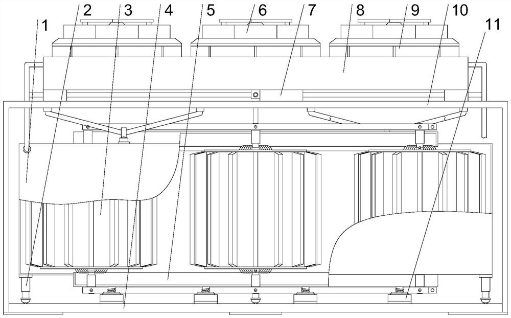
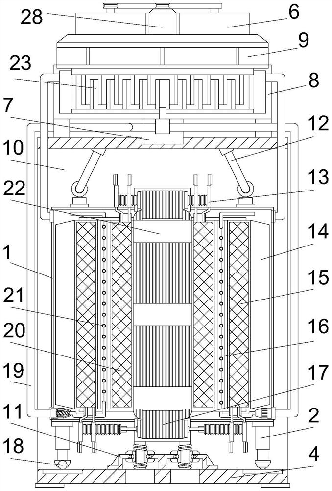
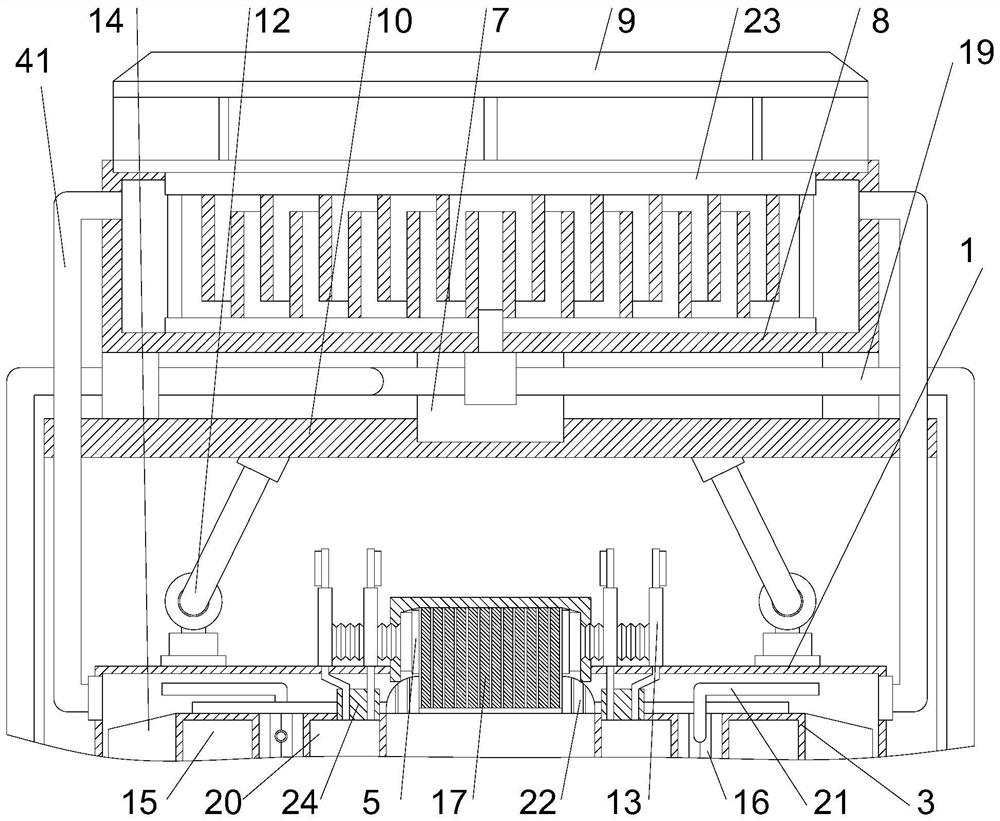
[0027] Such as Figure 1-Figure 8 As shown, a high-power power transformer according to the present invention includes a casing 1, a gantry 10, an air-cooled module, a water tank 8, a shock absorbing mechanism, a water distributor and a winding structure, and the bottom of the gantry 10 is fixedly installed There is a bottom plate 4, a steel cable 12 is fixedly installed on the inner wall of the top of the bottom plate 4, a ring frame is installed on the outer middle part of the steel cable 12, a shell 1 is fixedly installed on the bottom end of the ring frame, a water tank 8 is fixedly installed on the top of the gantry frame 10, and the water tank 8. A heat exchange frame 23 is fixedly installed in the middle part of the inner side. An air-coole...


PUM


Abstract

The invention relates to the field of power supply equipment, in particular to a high-power power supply transformer which comprises a shell, a portal frame, an air cooling module, a water tank, a damping mechanism, a water distributor and a winding structure. A bottom plate is fixedly installed at the bottom end of the portal frame, a steel cable is fixedly installed on the inner wall of the top end of the bottom plate, and an annular frame is installed in the middle of the outer side of the steel cable in a sleeving mode; a water tank is fixedly installed at the top end of the portal frame, a heat exchange frame is fixedly installed in the middle of the inner side of the water tank, and an air cooling module matched with the heat exchange frame is fixedly installed at the top end of the water tank. And through the arrangement that the water distributor is matched with the thin-walled pipe, it can be guaranteed that when water pressure fluctuates, a heat exchange medium still stably enters the thin-walled pipe, the heat exchange medium is matched with the medium entering the shell, heat absorption can be conducted on the winding structure from the inside and the outside, and the heat dissipation effect is guaranteed.

Description

technical field [0001] The invention relates to the field of power supply equipment, in particular to a high-power power supply transformer. Background technique [0002] The power transformer is a soft magnetic electromagnetic component. Its functions are power transmission, voltage conversion and insulation isolation. It is widely used in power supply technology and power electronics technology. According to the size of the transmission power, the power transformer can be divided into several grades: 10kVA The above is high power, 10kVA~0.5kVA is medium power, 0.5kVA~25VA is low power, and below 25VA is micro power. It should be self-evident that the design of the power transformer is different for different transmitted power. [0003] The iron core of the existing power transformer adopts a stacked iron core, but the windings of the iron core are loosely arranged, the iron core is large in size but the utilization rate is low, which affects the manufacturing cost and ope...

Claims


Application Information

Patent Timeline
Patent Type & Authority Applications(China)
IPC IPC(8): H01F27/28H01F27/16H01F27/22H01F27/06H01F27/08F16F15/02F16F15/067
CPCH01F27/2876H01F27/16H01F27/085H01F27/22H01F27/06F16F15/022F16F15/067
Inventor 王首权孙信
Owner 王首权
Why Eureka
Try Eureka