Oil well pump for well washing

An oil pumping and well cleaning technology, applied in the direction of pumps, pump components, and parts of pumping devices for elastic fluids, etc. Efficiency of oil intake, improvement of filling degree, effect of improving filling degree

Active Publication Date: 2022-04-29
DONGYING BAIHUA GASOLINEEUM TECH DEV
View PDF3 Cites 0 Cited by
  • Summary
  • Abstract
  • Description
  • Claims
  • Application Information

AI Technical Summary

Problems solved by technology

[0003] The purpose of the present invention is to clean the outer surface of the sand control cylinder through the cleaning plate on the vertical rod, clean the attached sand, and then improve the oil inlet efficiency of the equipment, so that the spoiler can stir the crude oil, so that the crude oil It is mixed with the gas, so it can not only achieve the effect of sand prevention and self-cleaning on the equipment, but also help to improve the filling degree of the equipment pumping. By forcing the positioning valve ball to open, the filling degree of the pump chamber can be increased to avoid As a result, the "air lock" phenomenon occurs after the opening of the positioning valve ball of the oil well pump, which solves the existing problem of the opening lag of the positioning valve ball. Leakage, brought to the ground to pollute the environment

Method used


Image

  • Oil well pump for well washing
  • Oil well pump for well washing
  • Oil well pump for well washing

Examples


Embodiment 1

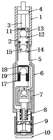
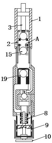
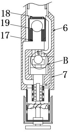
[0023] Example 1: See Figure 1-8 As shown, the present invention is an oil well pump for well cleaning, which includes a pump cylinder 1. An extended plunger 2 is slidably connected to the inside of the pump cylinder 1, and an oil pulling rod 3 is fixedly connected to the upper surface of the extended plunger 2. By reciprocating pulling Pull the oil rod 3, so that the oil pull rod 3 drives the extended plunger 2 to reciprocate up and down inside the pump barrel 1, and a guide mechanism 4 is arranged outside the pump barrel 1 outside the oil pull rod 3, and the pump barrel 1 The lower end of the upper joint 5 is fixedly connected with the upper joint 5, and the lower end of the upper joint 5 is fixedly connected with the thick tube 6, and the end of the thick tube 6 away from the upper joint 5 is fixedly connected with the oil drain mechanism 7, and the lower end of the oil drain mechanism 7 is fixedly connected with the oil inlet tube 8, and the oil inlet cylinder 8 and the c...

Embodiment 2

[0024] Embodiment 2: The internal rotation of the sand control cylinder 9 is connected with a cleaning assembly 10, and the cleaning assembly 10 includes a driven shaft 101, and a driven fan 102 is sleeved on the outside of the driven shaft 101. As the equipment performs an upstroke, the crude oil From the sand control cylinder 9 to the inside of the oil inlet cylinder 8, the crude oil has fluidity, and then the crude oil drives the driven fan 102 outside the driven shaft 101 to rotate during the flow, and the lower end of the driven shaft 101 is fixedly connected with The base 104 and the outside of the driven shaft 101 are sleeved with a positioning sleeve 103, and the positioning sleeve 103 is movably connected with the sand control cylinder 9, and when the driven fan 102 drives the driven shaft 101 to rotate, the driven shaft 101 drives the positioning The shaft sleeve 103 then rotates, and then generates the power of the transmission, and the two sides of the positioning s...

Embodiment 3

[0025] Embodiment 3: When cleaning the equipment, the extended plunger 2 is taken out from the inside of the pump barrel 1 through the oil rod 3, and then the inside of the pump barrel 1 is pressed. As the internal pressure of the pump barrel 1 is constantly changing large, and then the pressure above the oil drain mechanism 7 is greater than the pressure below, and the oil drain mechanism 7 includes the oil drain tube 01, and the inside of the oil drain tube 01 is fixedly connected with the fixed rod 02, and the inside of the oil drain tube 01 is located in the fixed plug ball The top of 04 is fixedly connected with return pipe 06, the upper end of fixed rod 02 is sleeved with telescopic rod 03, and the side of telescopic rod 03 away from fixed rod 02 is fixedly connected with fixed blocking ball 04 inside, and the upper surface of fixed blocking ball 04 is fixed Connect the limit spring 05, the end of the limit spring 05 away from the fixed ball 04 is fixedly connected with t...


PUM


Abstract

The invention relates to the technical field of oil well pump equipment, in particular to an oil well pump for well washing, which comprises a pump cylinder, a lengthened plunger is slidably connected in the pump cylinder, an oil pull rod is fixedly connected to the upper surface of the lengthened plunger, a guide mechanism is arranged outside the oil pull rod in the pump cylinder, and an upper joint is fixedly connected to the lower end of the pump cylinder. The lower end of the upper connector is fixedly connected with a thick cylinder, one end, away from the upper connector, of the thick cylinder is fixedly connected with an oil drainage mechanism, and the lower end of the oil drainage mechanism is fixedly connected with an oil inlet cylinder. Crude oil drives a driven fan outside a driven rotating shaft to rotate in the flowing process, a supporting rod drives a cleaning plate on a vertical rod to clean the outer surface of a sand prevention cylinder, the oil inlet efficiency of the equipment is improved, the crude oil is stirred through a spoiler, the crude oil and gas are mixed, and the oil inlet efficiency of the equipment is improved. Therefore, the sand prevention and self-cleaning effects on the equipment can be achieved, and the oil pumping filling degree of the equipment can be improved.

Description

technical field [0001] The invention relates to the technical field of oil well pump equipment, in particular to an oil well pump for well washing. Background technique [0002] The oil pump refers to the downhole device driven by the pumping unit to lift the crude oil in the well to the ground. It is mainly composed of four parts: the pump barrel, the suction valve, the piston and the discharge valve. According to the fixing method of the oil well pump in the well, it can be divided into tubular type pumps and rod pumps, and the existing drainable oil well pumps on the market mostly adopt the form of opening holes in the pump body to drain oil; a kind of oil well pump that can wash wells with positive circulation is disclosed in the announcement number CN203257647U. The oil pump includes a pump barrel, a sucker rod, and a piston. The rear end of the piston is connected to the sucker rod. There are sealing rings on both sides of the pump barrel, and there are horizontally p...

Claims


Application Information

Patent Timeline
IPC IPC(8): F04B47/00F04B53/12F04B53/10F04B53/14F04B53/20B01D29/64E21B43/00
CPCF04B47/00F04B53/14F04B53/126F04B53/1002F04B53/20B01D29/6476E21B43/121
Inventor 田彦鞠云忠成卫海张汉银胡驰尚同慧王修朝张明
Owner DONGYING BAIHUA GASOLINEEUM TECH DEV
Why Eureka
Try Eureka