


Quick Research
Generate reliable direction feasibility study reports for your R&D in just a few steps.

Technical Q&A
Discover and master advanced knowledge NOW. Basics, ideas, possibilities, all at once.

Find Solutions
As an expert in R&D theories, this can generate solutions to your technical problems instantly.

Evaluate Feasibility
Analyze your overall solution with one click, know your potential R&D risks in advance.

Monitor Landscape
Get weekly tech updates, stay abreast of the latest tech innovations and key insights.
High-speed angular contact bearing
An angular contact bearing, high-speed technology, used in rolling contact bearings, bearings, ball bearings, etc., can solve the problems of unreliable bearings, loose bearings, etc., to ensure stability, improve lubrication effect, and speed up oil intake efficiency. Effect
- Summary
- Abstract
- Description
- Claims
- Application Information
AI Technical Summary
Problems solved by technology
Method used
Image

Examples
specific Embodiment approach 1
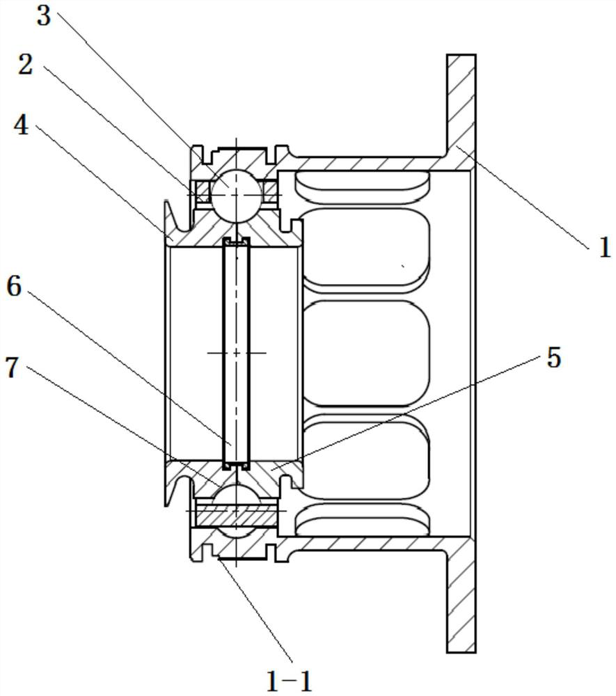
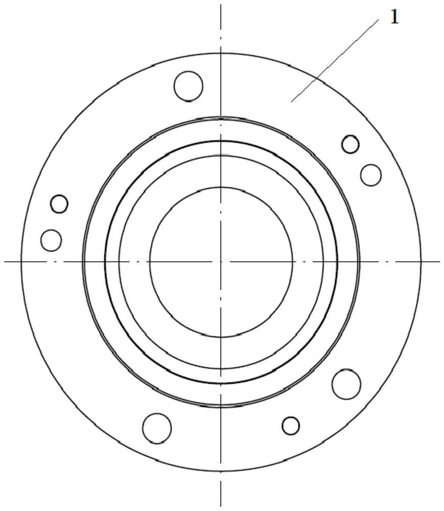
[0027] Specific implementation mode one: combine Figure 1 to Figure 8 This embodiment is described. A high-speed angular contact bearing of this embodiment includes a grooved ring 1 with spring support, a cage 2, a plurality of rolling elements 3, a first inner ring 4, a second inner ring 5 and an inner diameter clip 6 , the first inner ring 4 and the second inner ring 5 are arranged side by side from left to right and are connected by inner diameter clips 6 , a plurality of rolling elements 3 are installed on the first inner ring 4 and the second inner ring 5 through the cage 2 , with The elastic groove ring 1 is installed on the cage 2 and a plurality of rolling elements 3, and the outer wall of the elastic groove ring 1 corresponding to the oil inlet hole is provided with a U-shaped groove 1-1, and the U-shaped groove 1- 1 is provided with an annular groove 1-2 on one side, and the annular groove 1-2 is located outside the U-shaped groove 1-1.
[0028] In this embodiment,...
specific Embodiment approach 2
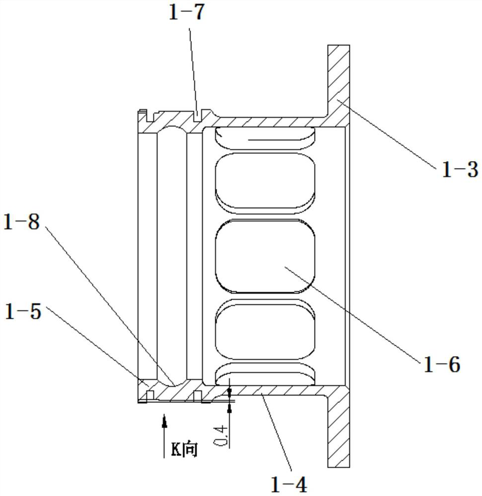
[0030] Specific implementation mode two: combination image 3 Describe this embodiment, the grooved ring 1 with elastic support of this embodiment includes flange plate 1-3, transition section 1-4 and installation section 1-5, flange plate 1-3, transition section 1-4 and installation section Sections 1-5 are sequentially connected from right to left and made into one body. The transition section 1-4 is provided with a plurality of strip-shaped holes 1-6 in the circumferential direction, and the outer wall of the installation section 1-5 is provided with two Groove 1-7, rolling element chute 1-8 is provided on the inner side wall of installation section 1-5. With such arrangement, the flanges 1-3 are convenient to be connected with related components. Other compositions and connections are the same as in the first embodiment.
specific Embodiment approach 3
[0031] Specific implementation mode three: combination image 3 The present embodiment will be described. The depth of the U-shaped groove 1-1 of the present embodiment is 4 mm. So set, it is convenient to fill lubricating oil. Other compositions and connections are the same as those in Embodiment 1 or Embodiment 2.
PUM
 Abstract
Description
Claims
Application Information
 - R&D Engineer
- R&D Manager
- IP Professional
- Industry Leading Data Capabilities
- Powerful AI technology
- Patent DNA Extraction
Browse by: Latest US Patents, China's latest patents, Technical Efficacy Thesaurus, Application Domain, Technology Topic, Popular Technical Reports.
© 2024 PatSnap. All rights reserved.Legal|Privacy policy|Modern Slavery Act Transparency Statement|Sitemap|About US| Contact US: help@patsnap.com