Vehicle-mounted compressor

A compressor, an integrated technology, applied in the field of compressors, can solve the problems of high cost, inconvenience, complex structure, etc.

Pending Publication Date: 2021-07-16
NINGBO BAOSI ENERGY EQUIP
View PDF0 Cites 0 Cited by
  • Summary
  • Abstract
  • Description
  • Claims
  • Application Information

AI Technical Summary

Problems solved by technology

In order to lubricate bearings and gears, current compressors are equipped with external oil tanks and oil pumps. This structure is complex and costly, and it is not convenient to use on vehicle compressors that require a compact structure.

Method used


Image

  • Vehicle-mounted compressor
  • Vehicle-mounted compressor
  • Vehicle-mounted compressor

Examples


Embodiment 1

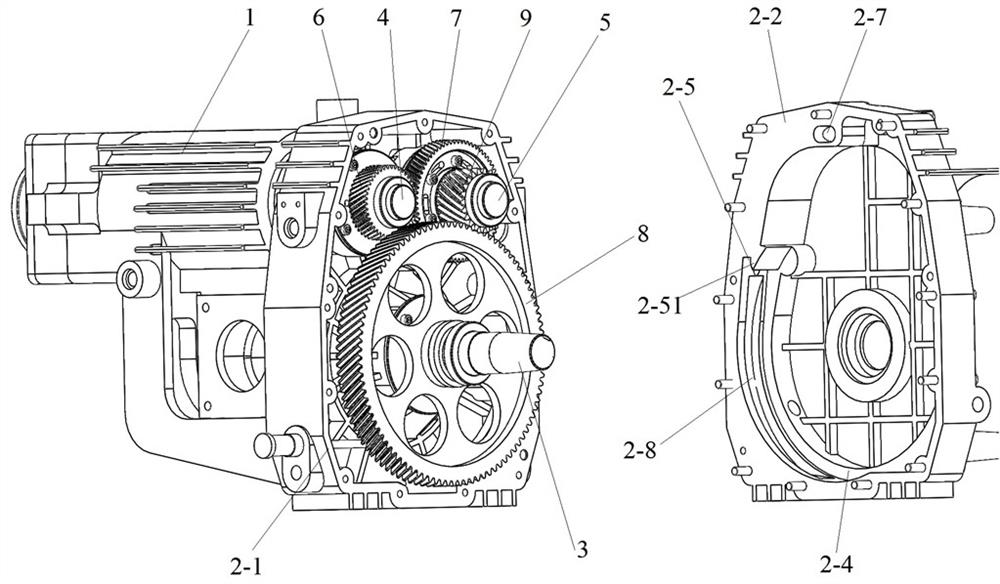
[0024] Such as figure 1 As shown in , the vehicle-mounted compressor of the present invention includes a cylinder 1, a gear box and a main shaft 3, the cylinder 1 is provided with a rotor I4 and a rotor II5, and the gear box is provided with a gear I6, a gear II7, a gear III8, a gear IV9, and a rotor I4 One end of rotor Ⅱ5 and rotor Ⅱ5 both extend into the gearbox, rotor Ⅰ4 is connected with gear Ⅰ6 in the gearbox, rotor Ⅱ5 is connected with gear Ⅱ7 and gear Ⅳ9 in the gearbox, and the main shaft 3 also extends into the gearbox and is in the gearbox It is connected with gear III8, gear III8 is meshed with gear IV9, and gear I6 is meshed with gear II7. The main shaft 3 is driven by an external drive source to drive the gear III8 to rotate, and the gear III8 meshes with the drive gear IV9 to rotate, and the rotor II5 rotates synchronously with the gear IV9 to make the gear II7 drive the gear I6 to rotate, so that the rotor I4 rotates synchronously with the gear I6. Main shaft 3 ...

Embodiment 2

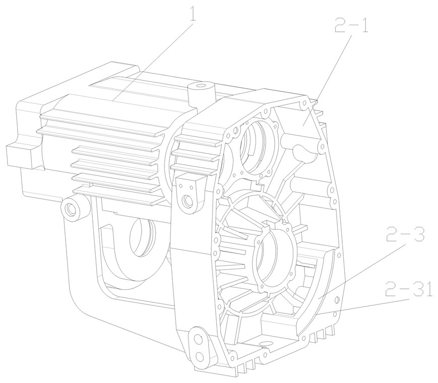
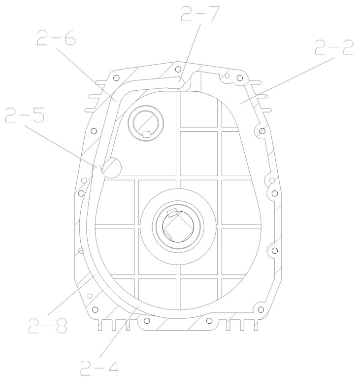
[0028] The difference between the vehicle-mounted compressor in this embodiment and Embodiment 1 is that an oil baffle 2-3 is provided on the middle and lower part of the inner wall of the box body 2-1, and the oil baffle plate 2-3 is integrally formed with the box body 2-1 cast, such as figure 2 shown in . Such as figure 1 , image 3 with Figure 4As shown in , the side of the cover body 2-2 corresponding to the oil baffle plate 2-3 is provided with an oil baffle wall 2-4, and the oil baffle wall 2-4 is located at the middle and lower part of the inner side wall of the cover body 2-2 and is connected with the The oil baffle 2-3 is opposite, and the oil baffle 2-4 and the oil passage 2-6 are integrally molded and cast with the cover 2-2, and the oil baffle 2-3, the oil baffle 2-4 and the cover 2- 2, the inner wall corresponding to the oil retaining wall 2-4 forms an oil retaining groove, the middle and lower part of the gear III 8 side and the oil guide groove 2-8 are loc...

Embodiment 3

[0031] The difference between the vehicle-mounted compressor of this embodiment and Embodiment 2 is that the side of the oil baffle 2-3 opposite to the cover 2-2 is also provided with an arc-shaped step surface 2-31, such as figure 2 As shown in , after the box body 2-1 and the cover body 2-2 are assembled left and right, the oil baffle plate 2-3 and the oil baffle wall 2-4 are respectively the groove walls of the oil baffle groove, and the arc-shaped step surface 2-31 The inner side wall corresponding to the oil retaining wall 2-4 in the cover body 2-2 is combined to form the groove bottom of the oil retaining groove, so that the width of the oil retaining groove is widened, and the gear III8 in the gear box is reduced. difficulty of assembly. The arc-shaped stepped surface 2-31 can be integrally molded and cast with the box body 2-1, or can be processed by turning or milling on the oil baffle plate 2-3.


PUM


Abstract

The invention provides a vehicle-mounted compressor which comprises an air cylinder, a gear box and a main shaft. A rotor I and a rotor II are arranged in the air cylinder; one end of the rotor I and one end of the rotor II extend into the gear box; a gear III connected with the main shaft and lubricating oil are arranged in the gear box; the lower part of the gear III is immersed in the lubricating oil; an oil guide groove opposite to the tooth surface of the lower middle part of the gear III is formed in the inner side wall of the gear box; the width of the oil guide groove is not larger than the width of the tooth surface of the gear III; an oil channel is further formed in the inner side wall of the gear box; an oil inlet and an oil outlet are formed in the two ends of the oil channel respectively; the oil inlet is opposite to the upper end of the oil guide groove; and the oil outlet is located above the rotor I and the rotor II. When the gear III rotates, the tooth surface of the gear III can throw lubricating oil in the gearbox into the oil guide groove, the lubricating oil enters the oil inlet along the oil guide groove under the action of centrifugal force and then flows onto the rotor I and the rotor II from the oil outlet along the oil channel, and the oil guide groove enables the oil to be concentrated and aligned with the oil inlet to flow, so that the oil inlet efficiency is improved.

Description

technical field [0001] The present invention relates to the technical field of compressors, and more specifically relates to a vehicle-mounted compressor. Background technique [0002] The application of oil-free screw compressors in food, medical, textile and other industries has attracted more and more attention from the public, especially when it is used to transport powder materials. It is necessary to ensure that there is no oil, but the bearings and gears on the rotor in the compressor still need lubricating oil for lubrication and cooling. In order to lubricate bearings and gears, current compressors are equipped with external oil tanks and oil pumps. This structure is complex and costly, and it is not convenient to use on vehicle compressors that require a compact structure. Contents of the invention [0003] The technical problem to be solved by the present invention is to provide a vehicle-mounted compressor, which has a compact structure and can supply oil and ...

Claims


Application Information

Patent Timeline
Patent Type & Authority Applications(China)
IPC IPC(8): F16H57/02F16H57/023F16H57/04F04C18/16F04C29/00F04C29/02
CPCF04C18/16F04C29/005F04C29/02F16H57/02F16H57/023F16H57/0421
Inventor 周武彬王立光胡世登夏志勇
Owner NINGBO BAOSI ENERGY EQUIP
Why Eureka
Try Eureka