
Printing and dyeing wastewater treatment device

A treatment device, a technology for printing and dyeing wastewater, applied in separation methods, filtration separation, chemical instruments and methods, etc., can solve the problems of difficult to filter impurities accumulation, affecting work efficiency, affecting filtration efficiency, etc., to improve filtration efficiency and use. High performance, strong adaptability, and the effect of avoiding the accumulation of impurities

Pending Publication Date: 2022-04-29
闫跃峰
View PDF7 Cites 2 Cited by
  • Summary
  • Abstract
  • Description
  • Claims
  • Application Information

AI Technical Summary

Problems solved by technology

[0005] Aiming at the deficiencies of the prior art, the present invention provides a printing and dyeing wastewater treatment device, which solves the problem that the traditional printing and dyeing wastewater is simple to filter, and some printing and dyeing wastewater contains a large amount of fine impurities such as cotton yarn and fiber. Filtering these tiny impurities will cause impurities to accumulate, which will easily cause blockage and affect the filtration efficiency. At the same time, the fine impurities will adhere to the filter screen, requiring a lot of manual cleaning, affecting work efficiency and reducing performance

Method used


Image

  • Printing and dyeing wastewater treatment device
  • Printing and dyeing wastewater treatment device
  • Printing and dyeing wastewater treatment device

Examples


Embodiment example 1

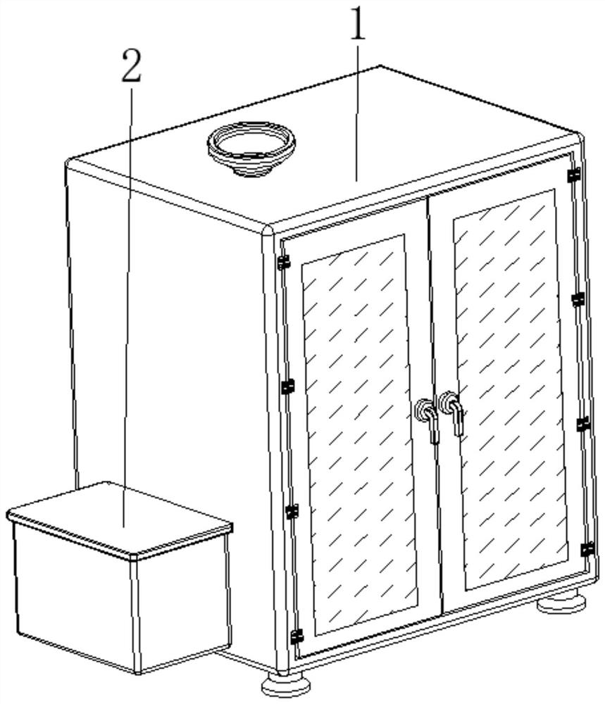
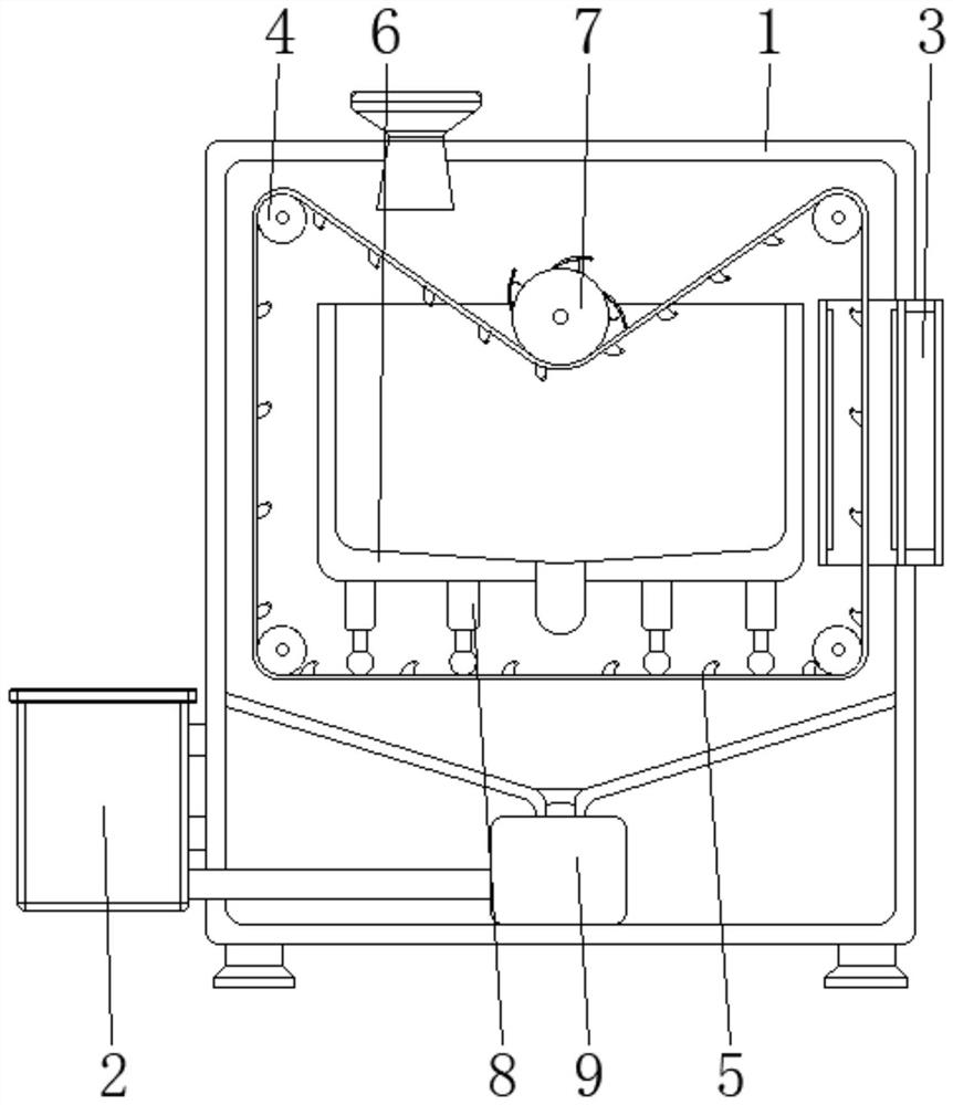
[0029] see Figure 1-6 , the present invention provides a technical solution: a printing and dyeing wastewater treatment device, including a box body 1, an impurity collection bin 2, and a heating mechanism 3, the impurity collection bin 2 is arranged on the bottom side of the surface of the box body 1, and the heating mechanism 3 is arranged on The top of the surface of the box body 1 and the side away from the impurity collection bin 2;

[0030] The inside of the box body 1 is provided with a driving roller 4, a conveying filter device 5, a water tank 6, a pressure roller device 7, a cleaning device 8, and an adsorption mechanism 9. The driving roller 4 is arranged inside the box body 1, and the conveying filter device 5 is arranged on the drive The surface of the roller 4 passes through the inside of the heating mechanism 3, the water tank 6 is arranged inside the box body 1, the pressure roller device 7 is rotatably connected between the two sides corresponding to the inne...

Embodiment example 2

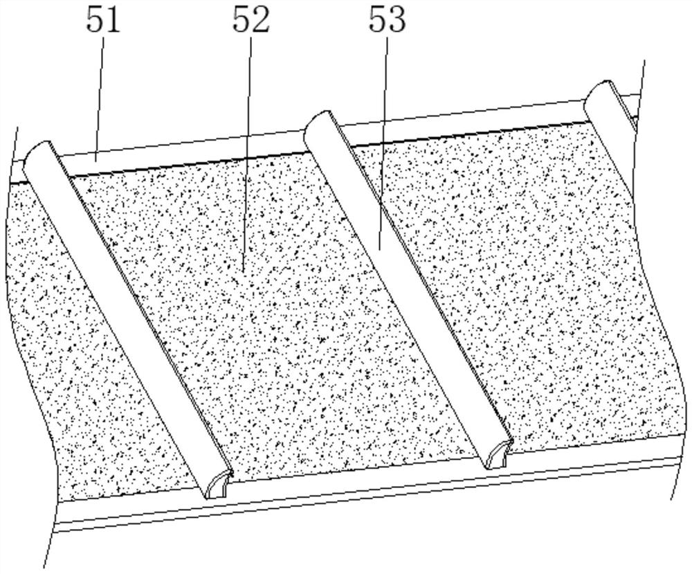
[0032] Conveying and filtering device 5 is provided with conveyor belt 51, elastic filter screen 52, curved surface scraper 53, and conveyor belt 51 is closed shape and is arranged on the surface of driving roller 4, and elastic filter screen 52 is arranged on the surface of conveyor belt 51, and arc surface The surface of the scraper 53 is fixedly connected to the surface of the conveyor belt 51. When the driving roller 4 drives the conveyor belt 51 through the curved scraper 53, the elastic filter 52 will also move accordingly. At this time, the printing and dyeing wastewater flows evenly to the elastic filter. The surface of the net 52 is filtered, and the accumulation of impurities can be avoided, which is helpful for filtering. At the same time, the cambered scraper 53 is used to cooperate with the driving roller 4 to achieve the purpose of synchronous operation, so as to prevent the viscous printing and dyeing wastewater Under the effect of, the phenomenon of slipping occ...

Embodiment example 3

[0034] The pressure roller device 7 is provided with a pressure roller main body 71, a pressure plate device 72, an arc spring 73, and an elastic bag 74. The end of the pressure roller main body 71 is rotatably connected to the inner wall of the water tank 6, and one end of the pressure plate device 72 is rotatably connected to the pressure roller. On the surface of the main body 71 , the elastic bag 74 is disposed between the surface of the platen device 72 and the corresponding two sides inside the main body 71 of the pressing roller.

[0035]The pressing plate device 72 is provided with an arc-shaped pressing plate 721 and an arc-shaped jet hole 722, and one end of the arc-shaped pressing plate 721 is rotationally connected to the surface of the roller main body 71. The arc-shaped air injection holes 722 are evenly distributed on the surface of the arc-shaped pressure plate 721. Using the pressing action of the pressure roller body 71, the conveyor belt 51 and the elastic fi...


PUM


Abstract

The invention discloses a printing and dyeing wastewater treatment device which comprises a box body, an impurity collecting bin and a heating mechanism, the impurity collecting bin is arranged on one side of the bottom of the surface of the box body, a driving roller is arranged in the box body, and a conveying and filtering device is arranged on the surface of the driving roller and penetrates through the interior of the heating mechanism. The water tank is arranged in the box body, the compression roller device is rotationally connected between the two corresponding sides of the inner wall of the water tank and located at the top, the cleaning device is arranged at the bottom of the water tank, and the adsorption mechanism is arranged at the bottom of the inner wall of the box body and connected with the impurity collecting bin in a matched mode. The invention relates to the technical field of sewage treatment equipment. According to the printing and dyeing wastewater treatment device, the effect of rapid filtration is achieved, fine impurities in printing and dyeing wastewater can be rapidly filtered, the adaptability is high, limitation is reduced, rapid self-cleaning can be carried out, impurity adhesion is reduced, the probability of blockage is low, and the filtration efficiency and the use performance are improved.

Description

technical field [0001] The invention relates to the technical field of sewage treatment equipment, in particular to a printing and dyeing wastewater treatment device. Background technique [0002] Printing and dyeing is a combination of physical and chemical treatment of textiles. For example, adding patterns and patterns on textiles, changing the color of textiles and related pretreatment processes, etc. Through the physical or chemical changes between the dye and the fiber, the textile will have a certain color and luster. According to different printing and dyeing objects, the printing and dyeing process can be divided into cotton textile printing and dyeing, linen textile printing and dyeing, wool textile dyeing and finishing, silk printing and dyeing, etc. With the continuous improvement and development of dyeing technology, the colors of textiles dyed in ancient my country have also been continuously enriched. The printing and dyeing industry should strengthen techn...

Claims


Application Information

Patent Timeline
Patent Type & Authority Applications(China)
IPC IPC(8): B01D33/056B01D33/04B01D33/54B01D33/66B01D33/76B01D33/80
CPCB01D33/056B01D33/04B01D33/54B01D33/66B01D33/76B01D33/801
Inventor 闫跃峰
Owner 闫跃峰
Learn More