
Permanent magnet energy-saving motor for mechanical equipment

A technology of mechanical equipment and electric motors, applied in the direction of controlling mechanical energy, electric components, electromechanical devices, etc., can solve the problems of cumbersome speed regulation operations, etc., and achieve the effect of improving heat exchange efficiency and having more speed regulation gears

Inactive Publication Date: 2022-04-26
DAQING RUISID PETROLEUM MASCH MFG CO LTD
View PDF1 Cites 1 Cited by
  • Summary
  • Abstract
  • Description
  • Claims
  • Application Information

AI Technical Summary

Problems solved by technology

[0006] In order to solve the problem of cumbersome mechanical speed regulation operation of existing permanent magnet motors, the present invention provides a permanent magnet energy-saving motor for mechanical equipment

Method used


Image

  • Permanent magnet energy-saving motor for mechanical equipment
  • Permanent magnet energy-saving motor for mechanical equipment
  • Permanent magnet energy-saving motor for mechanical equipment

Examples


Embodiment Construction

[0024] The present invention will be further described below in conjunction with accompanying drawing:

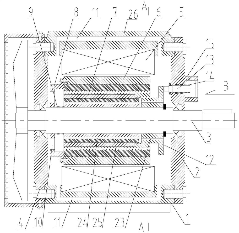
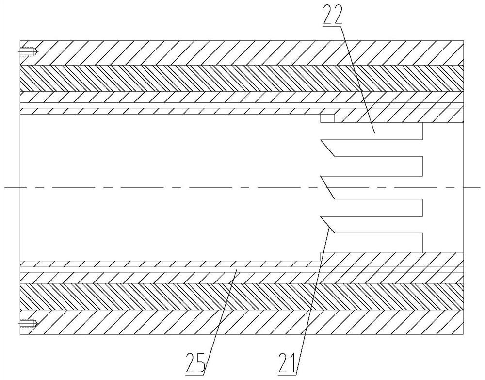
[0025] Depend on figure 1 combine Figure 2-9 As shown, a permanent magnet energy-saving motor for mechanical equipment includes a casing 1, a front end cover 2, a rear end cover 4, a motor shaft 3, a stator 5, a rotor and a fan, and the rotor is composed of an outer rotor 6 and an inner rotor 7. The inner hole of the rotor 6 is connected with the outer circle of the inner rotor 7 with clearance fit, and the outer rotor 6 and the inner rotor 7 are installed with evenly distributed permanent magnets 16 in the circumferential direction. Axis 3 is fixedly connected;

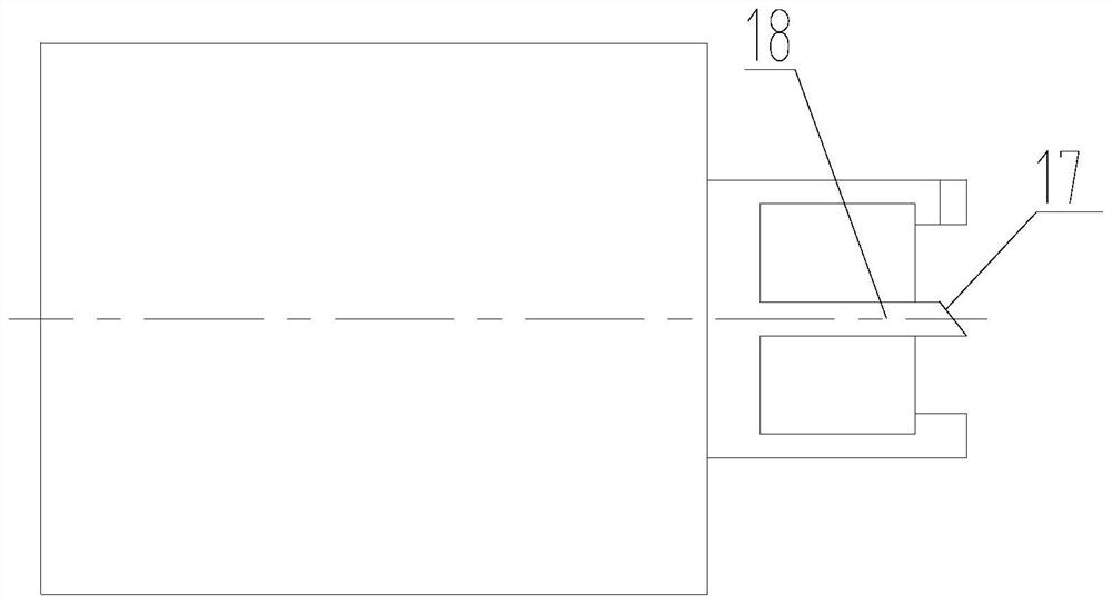
[0026] The right side of the inner rotor 7 is provided with sliding claws 18 uniformly distributed around the circumference, the right side of the sliding claws 18 is provided with a guide slope 17, the right side of the sliding claws 18 is provided with a push rod 12, and the push rod 12 is provided with guide...


PUM


Abstract

The invention provides a permanent magnet energy-saving motor for mechanical equipment. Relates to the technical field of oilfield downhole tools. The rotor is composed of an outer rotor and an inner rotor, an inner hole of the outer rotor is in clearance fit connection with the outer circle of the inner rotor, the outer rotor and the inner rotor are provided with uniformly distributed permanent magnets in the circumferential direction, the outer rotor is fixedly connected with a positioning sleeve, and the positioning sleeve is fixedly connected with the motor shaft. Compared with the prior art, the motor has the following beneficial effects that the inner rotor rotates once relative to the outer rotor every time the push rod is pressed through a pressing rotating mechanism composed of the sliding claws of the inner rotor, the indexing grooves of the outer rotor and the guide strips and the guide teeth of the push rod, multi-stage speed regulation can be achieved, speed regulation can be achieved without disassembling the motor, and the motor is simple and convenient to use and has multiple speed regulation gears; air flow in the motor is generated when the spiral blade rotates along with the rotor, forced air internal circulation is formed through the flow passing channel and the vent holes I, II and III, heat of the rotor is brought to the machine shell for heat dissipation, and the heat exchange efficiency of the motor is improved.

Description

Technical field: [0001] The invention relates to the technical field of permanent magnet motors, in particular to a permanent magnet energy-saving motor for mechanical equipment. Background technique: [0002] The motor is an electromagnetic device that realizes the conversion or transmission of electric energy according to the law of electromagnetic induction. The main function of the motor is to generate driving torque. As a power source, the speed-regulating motor is to change the speed of the motor by changing the number of motor stages, voltage, current, frequency, etc., so that the motor can achieve higher performance. The existing The speed control motor mainly uses electronic devices to achieve speed regulation, and electronic devices are prone to failure due to environmental influences after long-term use; [0003] The existing speed-regulating motor lacks a speed-regulating motor using mechanical speed regulation. The notification number CN 112366910B provides a r...

Claims


Application Information

Patent Timeline
Patent Type & Authority Applications(China)
IPC IPC(8): H02K16/02H02K1/28H02K9/06H02K5/20H02K5/18H02K1/32H02K7/00
CPCH02K16/02H02K1/28H02K9/06H02K5/20H02K5/18H02K1/32H02K7/003
Inventor 魏良艳李忠杨王天义
Owner DAQING RUISID PETROLEUM MASCH MFG CO LTD
Learn More