
Brake drum disc structure based on drum brake

A brake drum and disc structure technology, applied in the direction of drum brakes, brake actuators, brake parts, etc., can solve the problems that the brake drum cannot be released quickly, the braking performance is reduced, and the friction coefficient is reduced. The effect of avoiding thermal fading, good braking performance and high controllability

Pending Publication Date: 2022-04-26
萧懿
View PDF0 Cites 0 Cited by
  • Summary
  • Abstract
  • Description
  • Claims
  • Application Information

AI Technical Summary

Problems solved by technology

[0006] The invention provides a brake drum disc structure based on the drum brake, which can be automatically switched according to the temperature of the friction plate on it, so that it will not experience thermal decay during the long-term braking process, so that the The drum brake always maintains the advantages of good braking performance, high safety and reliability, and solves the problem of friction between the friction plate in the existing drum brake and the brake plate rotating with the wheel. Mutual friction will generate a lot of heat, which cannot be dissipated quickly in the sealed brake drum, causing the temperature of the friction plate on it to rise rapidly with the braking time, and the friction is easily caused by the phenomenon of thermal decay The friction coefficient on the surface of the disc decreases, the braking performance decreases and the braking distance becomes longer, resulting in a greater safety hazard when performing braking for a long time

Method used


Image

  • Brake drum disc structure based on drum brake
  • Brake drum disc structure based on drum brake
  • Brake drum disc structure based on drum brake

Examples


Embodiment Construction

[0024] The following will clearly and completely describe the technical solutions in the embodiments of the present invention with reference to the accompanying drawings in the embodiments of the present invention. Obviously, the described embodiments are only some, not all, embodiments of the present invention. Based on the embodiments of the present invention, all other embodiments obtained by persons of ordinary skill in the art without making creative efforts belong to the protection scope of the present invention.

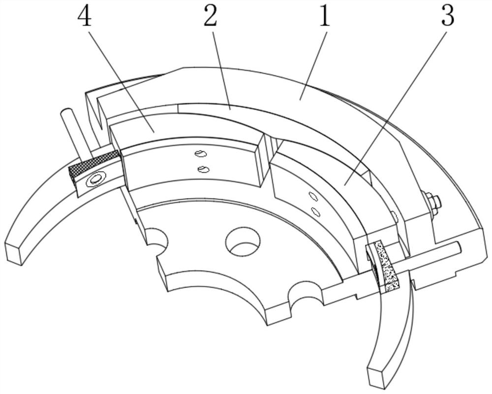
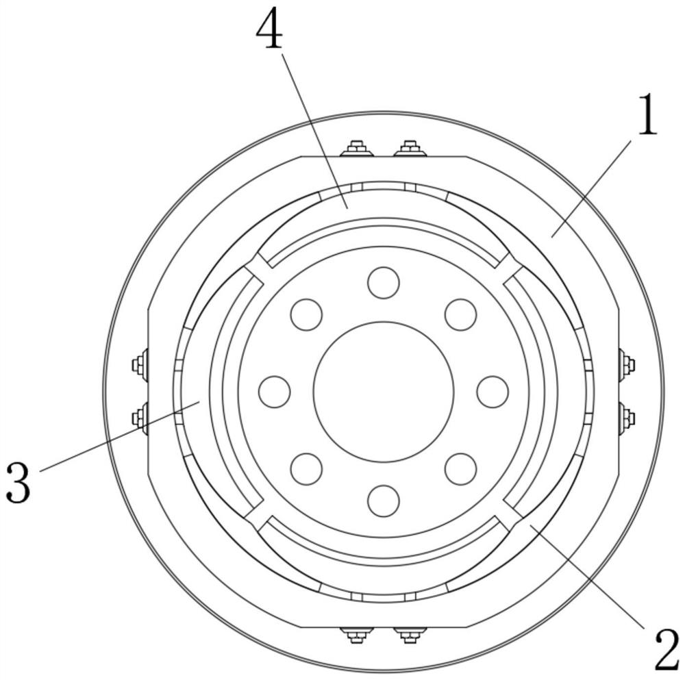
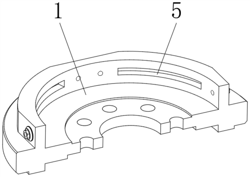
[0025] see figure 1 , a brake drum disc structure based on drum brakes, including a brake drum 1, a movable block 2, a first friction assembly 3 and a second friction assembly 4, such as image 3 As shown, the inner side of the brake drum 1 is provided with four sets of limit card slots 5 arranged in a circular array, such as Figure 4 As shown, the outer surface of the movable block 2 is fixedly mounted with a connecting slider 6 to be movably socketed with ...


PUM


Abstract

The invention relates to the technical field of drum brakes, and discloses a drum brake based brake drum disc structure which comprises a brake drum, a movable clamping block, a first friction assembly and a second friction assembly. A connecting sliding block is fixedly installed on the outer surface of the movable clamping block so as to be movably connected with a limiting clamping groove in the brake drum in a sleeved mode, and first friction assemblies with the two sides of the outer surface matched with the arc-shaped curved surfaces on the first friction assemblies are fixedly installed at the left end and the right end of an inner cavity of the brake drum and located on the inner side of the movable clamping block. According to the brake drum disc structure based on the drum brake, the first friction assembly and the second friction assembly are arranged, so that the working states of the first friction assembly and the second friction assembly are automatically adjusted according to temperature changes in the vehicle braking process; the heat fading phenomenon caused by the fact that the temperature of the first friction lining on the first friction assembly is too high during long-time braking operation is effectively avoided.

Description

technical field [0001] The invention relates to the technical field of drum brakes, in particular to a drum brake-based brake drum disc structure. Background technique [0002] As one of the commonly used braking forms of automobiles, drum brakes mainly use the friction between the stationary brake pads and the inner surface of the brake drum rotating with the wheels to generate corresponding frictional braking force to force the vehicle to decelerate. Compared with disc brakes, drum brakes can generate strong frictional braking force due to their self-braking effect, making them widely used in the braking of large vehicles. [0003] However, when the friction lining in the drum brake rubs against the brake lining that rotates with the wheel, more heat will be generated due to mutual friction between the two, and it cannot be dissipated quickly in the sealed brake drum, causing its The temperature of the upper friction plate rises rapidly with the braking time, and the fric...

Claims


Application Information

Patent Timeline
Patent Type & Authority Applications(China)
IPC IPC(8): F16D51/10F16D65/09F16D65/14F16D121/14
CPCF16D51/10F16D65/09F16D65/14F16D2121/14
Inventor 萧懿
Owner 萧懿
Learn More