Shaping device of precise continuous cold punching die

A shaping device and continuous technology, applied in the fields of forming tools, manufacturing tools, metal processing equipment, etc., can solve the problems of time-consuming and labor-intensive, troublesome installation and disassembly, and achieve the effect of ensuring accurate installation, improving heat dissipation efficiency, and ensuring stability

Active Publication Date: 2022-04-26
东台威达鑫精密模具有限公司
View PDF5 Cites 0 Cited by
  • Summary
  • Abstract
  • Description
  • Claims
  • Application Information

AI Technical Summary

Problems solved by technology

[0006] The main purpose of the present invention is to provide a shaping device for precision continuous cold stamping dies, which solves the problem of time-consuming and labor-intensive installation and disassembly when a fan is installed in the inner cavity of the base

Method used


Image

  • Shaping device of precise continuous cold punching die
  • Shaping device of precise continuous cold punching die
  • Shaping device of precise continuous cold punching die

Examples


Embodiment 1

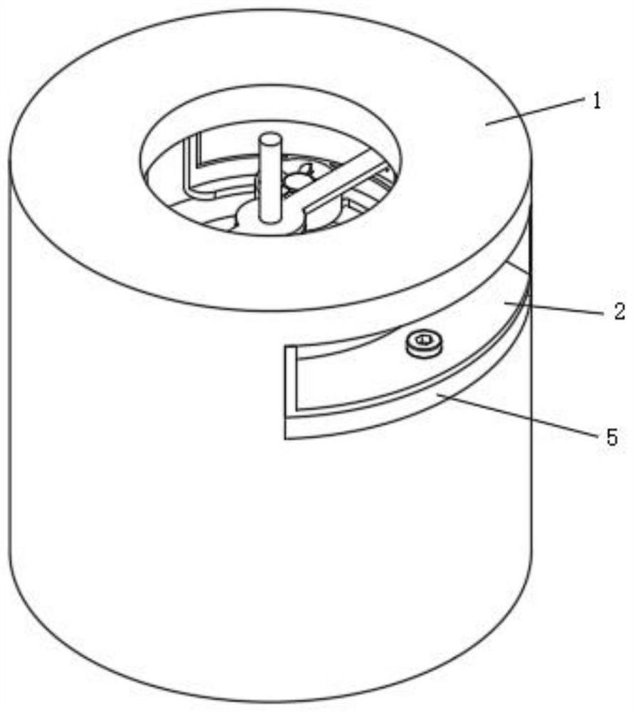
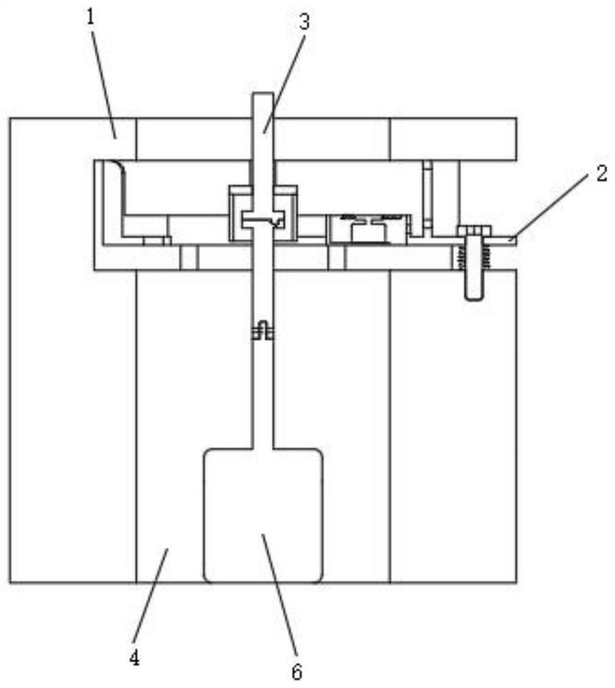
[0033] Such as figure 1 , 2 , 3, 4, 5, 6, and 7, a shaping device for a precision continuous cold stamping die, including a base 1, a through hole 4 and a drive motor 6, the end face of the base 1 is provided with a through hole 4, the through hole 4 A drive motor 6 is provided at the bottom of the hole;

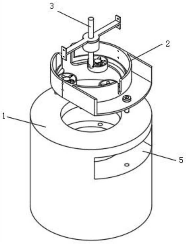
[0034] The upper part of the side wall of the base 1 is provided with an embedding groove 5, and a quick-mounting heat sink 2 is embedded in the groove of the embedding groove 5, and the interior of the quick-mounting heat sink 2 is provided with a quick-mounting limiter adapted to the drive motor 6 3;

[0035] The quick-mounted cooling device 2 includes a quick-mounted seat 201, an inner ring 202, a mounting cover 203, a fan 204, a wire hole 205, a docking hole 206, a gap 207, a groove 208, a jack 209, a fastening bolt 210, a spring 211 and Limiting post 212, in the groove of embedding groove 5, be embedded with fast loading seat 201, the upper end of fast loading seat 2...

Embodiment 2

[0038] Such as figure 1 , 2 , 3, 4, and 7, wherein the same or corresponding components as those in Embodiment 1 are designated with reference numerals corresponding to Embodiment 1. For the sake of brevity, only the differences from Embodiment 1 are described below. The difference is that the quick-installation cooling device 2 also includes a screw hole 213, the inner wall of the quick-installation seat 201 is provided with a screw hole 213, and the quick-installation limiting device 3 includes a connecting frame 301, a limit cover 302, a quick-installation Rod 303, connecting head 304, connecting seat 305 and fixed rod 306, the inner side wall of quick mounting seat 201 is provided with screw hole 213 places and is connected with connecting frame 301, and the middle part of the lower end of connecting frame 301 is provided with limit cover 302, and connecting frame 301 A quick-loading rod 303 is inserted into the opening in the middle of the upper end of the upper end, the...


PUM


Abstract

The invention relates to the technical field of cold stamping die machining, in particular to a shaping device of a precise continuous cold stamping die, and aims to solve the problem that when a fan is arranged in an inner cavity of a base, mounting and dismounting are troublesome, time-consuming and labor-consuming, the following technology is adopted: a quick mounting seat is embedded in a groove of an embedding groove, and a butt joint hole is formed in the upper end of the quick mounting seat; a notch is formed in the side wall of the quick mounting seat, an inner ring is arranged at the inner bottom of the quick mounting seat, three mounting covers are arranged on the side wall of the inner ring of the quick mounting seat, a fan is arranged in each mounting cover, a wire hole is formed in the side wall of each mounting cover and communicated with a wire wiring groove between the inner ring and the quick mounting seat, and a groove is formed in the outer side of the quick mounting seat. Due to the fact that the quick mounting seat, the limiting column, the fastening bolt and the spring are matched with the base, quick mounting and dismounting between the quick mounting seat and the base can be achieved through the fastening bolt and the spring, limiting mounting between the quick mounting seat and the base can be achieved through matching of the limiting column and the base, and accurate mounting of the quick mounting seat is guaranteed.

Description

technical field [0001] The invention relates to the technical field of cold stamping die processing, in particular to a shaping device for a precision continuous cold stamping die. Background technique [0002] Cold stamping die is a kind of die, which exerts deformation force on the sheet placed inside at room temperature. It is a special special tool for product parts with certain shape, size and performance, which is installed on the press and exerts deformation force at room temperature. It can usually process the sheet into a specified shape, and now the precision of the cold stamping die is very high; [0003] The Chinese utility model patent application number is CN202022548697.X, and the patent name is a shaping device for a precision continuous cold stamping die. The inside of the installation cavity is fixedly connected with an organic base, the inner side of the base is clamped with a motor, the output shaft of the motor is fixedly connected with a center plate, ...

Claims


Application Information

Patent Timeline
Patent Type & Authority Applications(China)
IPC IPC(8): B21D37/10B21D37/16
CPCB21D37/10B21D37/16Y02P70/10
Inventor 张琳王文峰
Owner 东台威达鑫精密模具有限公司
Why Eureka
Try Eureka