
Structure and working method of a tiltrotor unmanned aerial vehicle

A technology of tilting mechanism and tilting rotor, applied in the direction of rotorcraft, unmanned aerial vehicle, motor vehicle, etc., can solve the problems such as limited ability to adjust the direction of lift vector, inability to work close to the building surface, instability, etc. Achieve the effect of realizing high-tech measurement operations, simple structure, and ensuring stability

Active Publication Date: 2022-06-21
BEIJING UNIV OF POSTS & TELECOMM
View PDF0 Cites 4 Cited by
  • Summary
  • Abstract
  • Description
  • Claims
  • Application Information

AI Technical Summary

Problems solved by technology

[0003] With the rapid expansion of the application field of UAVs, the load of UAVs and the multi-purpose of UAVs are getting higher and higher. By setting up multi-rotors on the aircraft, the lift of the aircraft will be significantly improved under the premise that the weight of the aircraft does not increase much. , has the advantages of strong load capacity, high controllability, flexible movement, and good fault tolerance. However, the rotors of multi-rotor UAVs are currently installed in a fixed way, and the direction adjustment ability of the generated lift vector is limited, and only vertical take-off and landing can be achieved. And the ability to fly in the air mainly depends on the rotation speed of different rotor blades of the UAV to adjust the direction of the UAV. It is vulnerable to environmental influences such as wind and unstable during the work process. Moreover, UAVs are now mainly used for aerial flight surveys work, unable to meet the requirements of working close to the surface of the building

Method used


Image

  • Structure and working method of a tiltrotor unmanned aerial vehicle
  • Structure and working method of a tiltrotor unmanned aerial vehicle
  • Structure and working method of a tiltrotor unmanned aerial vehicle

Examples


Embodiment Construction

[0033] In order to make those skilled in the art better understand the solutions of the present invention, the technical solutions in the embodiments of the present invention will be clearly and completely described below with reference to the accompanying drawings in the embodiments of the present invention. Obviously, the described embodiments are only Embodiments are part of the present invention, but not all embodiments. Based on the embodiments of the present invention, all other embodiments obtained by persons of ordinary skill in the art without creative efforts shall fall within the protection scope of the present invention.

[0034] It should be noted that the terms "first", "second" and the like in the description and claims of the present invention and the above drawings are used to distinguish similar objects, and are not necessarily used to describe a specific sequence or sequence. It is to be understood that the data so used may be interchanged under appropriate ...


PUM


Abstract

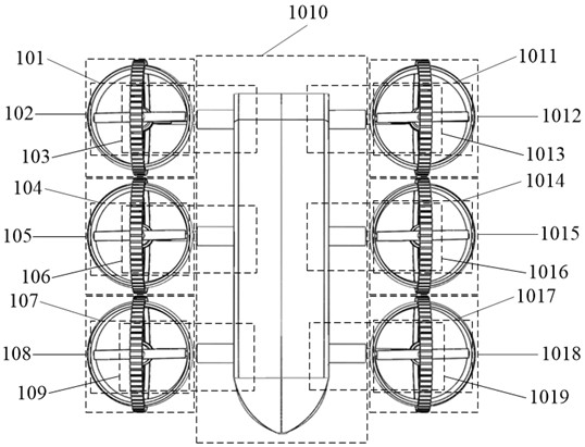
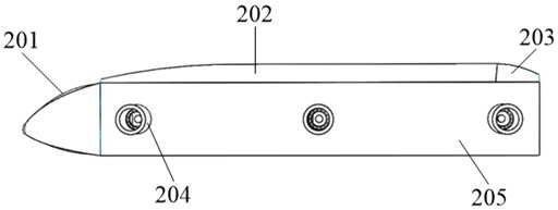
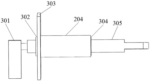
The invention discloses a tiltrotor unmanned aerial vehicle structure and its working method. By setting the duct roller on the outer ring of the turbine cover and being able to rotate relative to the turbine cover, the axis of the duct roller and the axis of the transmission shaft of the tilting mechanism Parallel; directly connected to the turbine cover through the transmission shaft of the tilting mechanism, and a fan blade power mechanism for providing power is provided in the turbine cover. At the same time, the ducted rollers are set on the outer ring of the turbine cover, and the turbine cover and the ducted rollers form a circular protection for the fan blade power mechanism at the same time. The shaft rotates to adjust the direction of the turbine cover, thereby adjusting the overall power output direction of the smart drone. The flight of this model realizes multifunctional use.

Description

technical field [0001] The invention belongs to the technical field of vector tilting unmanned aerial vehicles, and particularly relates to a tilting rotor unmanned aerial vehicle structure and a working method thereof. Background technique [0002] The unmanned aircraft operated by radio remote control equipment and self-provided program control device, that is, the development of UAV technology, has no cockpit on board, but is equipped with autopilot, program control device and other equipment. The personnel on the ground, on the ship or in the remote control station of the mother machine use radar and other equipment to track, locate, remote control, telemetry and digital transmission. It can take off like a normal plane under radio control or launch with a booster rocket. When recovered, it can be automatically landed in the same way as the landing process of ordinary aircraft, or it can be recovered by remote control with parachute or block; it can be used repeatedly. ...

Claims


Application Information

Patent Timeline
Patent Type & Authority Patents(China)
IPC IPC(8): B64C27/52B64C27/08
CPCB64C27/52B64C27/08B64U30/20B64U50/19B64U10/10B64U2101/00
Inventor 王泽瑜
Owner BEIJING UNIV OF POSTS & TELECOMM
Learn More