Automatic steel slag cake pressing and efficient cake discharging device for steel machining
A steel slag, automatic technology, applied in presses, manufacturing tools, transportation and packaging, etc., can solve problems such as reduced work efficiency, and achieve the effect of improving efficiency, convenient manual operation and saving manpower
- Summary
- Abstract
- Description
- Claims
- Application Information
AI Technical Summary
Problems solved by technology
Method used
Image
Examples
Embodiment 1
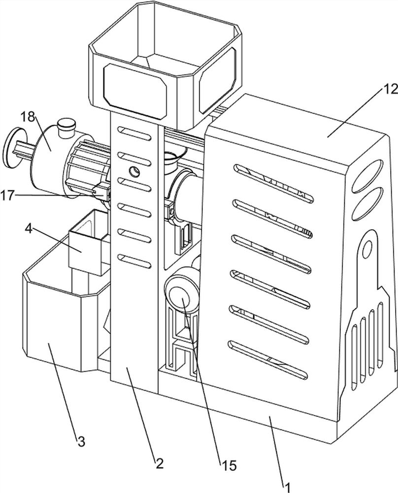
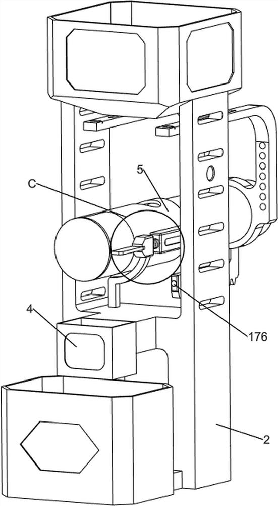
[0041] A kind of steel slag automatic cake pressing device for steel processing, such as Figure 1-9 Shown, including the base plate 1, the first support base 2, the material box 3, the guide sleeve 4, the pressure drum 5, the discharge baffle 6, the second support seat 7, the press block 8, the first push rod 9, the second push rod 10, the first guide rod 11, the shell 12, the steel slag box 13, the retaining mechanism 14 and the pressing mechanism 15, the bottom plate 1 left is connected to the first support seat 2, the first support base 2 is connected to the lower left side of the bin 3 and the guide sleeve 4, the guide sleeve 4 is located above the tank 3, the first support base 2 is connected to the middle of the second support base 7, The second support base 7 is connected to the pressure drum 5, the pressure bucket 5 is opened with an inlet hole at the top, the lower left side of the pressure bucket 5 is articulated with the discharge baffle 6, the pressure drum 5 slide is ...
Embodiment 2
[0047] On the basis of Example 1, e.g., Figure 2 、 Figure 9 、 Figure 10 、 Figure 11 、 Figure 12 and Figure 13 Shown, further comprising a lid opening mechanism 16, the opening mechanism 16 for pushing the wedge block 143 to move, the opening mechanism 16 includes a first fixed rod 161, a push plate 162, a third reel 163 and a second torsion spring 164, the first push rod 9 left rotating type connection has two third hinges 163, two third hinges 163 minutes front and rear settings, the third hinge 163 is connected to the push plate 162, the push plate 162 is used to push the wedge block 143 to move, Between the two second guide rods 144 is connected to the first fixing rod 161, the push plate 162 can squeeze the first fixing rod 161 to move, the push plate 162 and the first push rod 9 are connected to the two second torsion springs 164, the second torsion spring 164 is set on the third reel 163.
[0048] The first pusher 9 drives the third shaft 163, the push plate 162 and the sec...
Embodiment 3
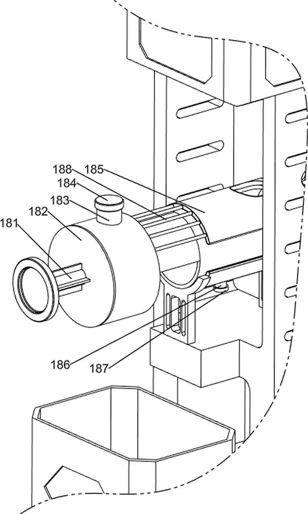
[0052] On the basis of Example 2, e.g., Figure 1 、 Figure 2 、 Figure 3 、 Figure 4 、 Figure 14 、 Figure 15 and Figure 16Shown, further comprising a cooling mechanism 18, a cooling mechanism 18 for cooling the press barrel 5, the cooling mechanism 18 includes a pusher with a piston 181, a water injection cylinder 182, an inlet pipe 183, an inlet end cover 184, a water guide arc plate 185, an outlet pipe 186, an outlet end cover 187 and a conduit 188, a water injection barrel 5 is connected to the left side of the water injection cylinder 182, the water injection cylinder 182 inner sliding connection has a piston pusher 181, the water injection cylinder 182 is connected to the top middle with an inlet pipe 183, The top of the inlet pipe 183 is provided with an inlet end cover 184, the inlet end cover 184 is a removable setting, the right side of the water injection cylinder 182 is connected along the arc even interval to connect multiple catheters 188, multiple catheters 188 are c...
PUM
 Abstract
Description
Claims
Application Information
 - R&D Engineer
- R&D Manager
- IP Professional
- Industry Leading Data Capabilities
- Powerful AI technology
- Patent DNA Extraction
Browse by: Latest US Patents, China's latest patents, Technical Efficacy Thesaurus, Application Domain, Technology Topic, Popular Technical Reports.
© 2024 PatSnap. All rights reserved.Legal|Privacy policy|Modern Slavery Act Transparency Statement|Sitemap|About US| Contact US: help@patsnap.com


