Molding method of casting

A casting and parting surface technology, which is applied to the modeling field of castings, can solve the problems of high casting cost and long cycle of castings, and achieve the effects of reducing casting cost, simple steps and shortening production cycle.

Active Publication Date: 2022-04-22
KOCEL STEEL
View PDF5 Cites 0 Cited by
  • Summary
  • Abstract
  • Description
  • Claims
  • Application Information

AI Technical Summary

Problems solved by technology

[0006] The purpose of the present invention is to provide a molding method for castings, in particular to a molding method for ring castings, so as to solve the problems of high casting cost and long cycle time in the prior art.

Method used


Image

  • Molding method of casting
  • Molding method of casting
  • Molding method of casting

Examples


Embodiment 1

[0032] Embodiment one: a molding method of a casting, specifically comprising the following steps:

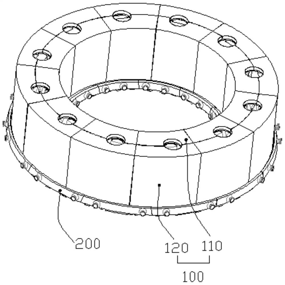
[0033] Molding scheme design: use the end face of the casting as the parting surface to divide the upper box and the lower box for molding; according to the casting structure and modeling accuracy, the overall sand core of the casting is divided into the main sand core 100 and the tire plate sand core 200.

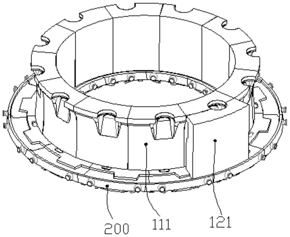
[0034] Sand core production: 3D printing is used to make each sand core, and the positioning reference for placing the main sand core 100 is set on the tire plate sand core 200, wherein the positioning reference follows the end face contour of the casting; the main sand core 100 is divided into inner ring sand cores 110 and outer ring sand core 120, the inner ring sand core 110 is used to form the inner ring structure of the casting, and the outer ring sand core 120 is used to form the outer ring structure of the casting; the tire plate sand core 200 is divided into a refere...

Embodiment 2

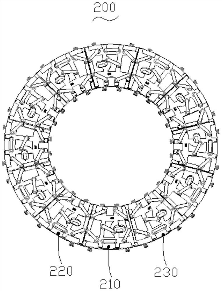
[0039] Embodiment 2: On the basis of the steps in Embodiment 1, the inner ring sand core 110 is divided into several inner ring sand core modules 111, and the outer ring sand core 120 is divided into several outer ring sand core modules 121, and the cores are laid according to the sequence Numbering; the base core 210, each rotating core 220, and the bottom surface of the closed core 230 are provided with an anti-falling structure 240, a gate positioning structure 250, and a reinforcing rib 260; specifically, the reinforcing rib 260 is set in a grid shape to increase contact with the sand area to increase the strength of the rib 260.

[0040] It should be noted that when making sand cores, it is determined according to the printing range of the printer that the inner ring sand core 110 and the outer ring sand core 120 are divided into a reasonable number of corresponding sand core modules according to a certain angle to meet production requirements; The embodiment mainly relat...


PUM


Abstract

The invention belongs to the technical field of casting, and particularly relates to a molding method of a casting, which is used for realizing rapid manufacturing of a ring steel casting without manufacturing a mold. Modeling in a manner of dividing an upper box and a lower box by taking the end surface of a casting as a parting surface; a main body sand core and a bed mould sand core are manufactured, a positioning reference for placing the main body sand core is arranged on the bed mould sand core, the positioning reference follows the profile of the end face of the casting, and the main body sand core is divided into an inner ring sand core and an outer ring sand core; the bed mould sand core is divided into a reference core, a plurality of rotating cores and a closed core, and the matching surfaces of the reference core, the rotating cores and the closed core which are matched with one another are obliquely arranged; the standard core, the rotating cores and the closed core are assembled in sequence to form a bed mould sand core, quicksand molding is conducted, a pouring system is laid at the same time, and the box is turned over after molding sand is hardened; and upper box modeling: placing the inner ring sand core and the outer ring sand core on the lower box along the positioning reference to form a cavity of the casting, and performing quicksand modeling to finish upper box modeling.

Description

technical field [0001] The invention belongs to the technical field of casting, and in particular relates to a molding method of castings, which is used to realize rapid manufacturing of ring-type steel castings without making molds. Background technique [0002] In the prior art, the casting of ring-type steel castings adopts the combination of the lower box and the sand mold to form the cavity of the casting, so that the corresponding lower box tire plate and core box mold need to be made; the molding method of the prior art mainly has the following problems: [0003] 1. The mold base plate is generally made of wood or lost foam material. When making a large-diameter ring casting base plate, it needs to be made in pieces and then spliced ​​to complete, which makes the overall strength of the base plate poor, and it is easy to distort and deform during the overturning process. As a result, the size of the lower box is unqualified, which makes the positioning of the lower co...

Claims


Application Information

Patent Timeline
IPC IPC(8): B22C9/24B22C9/10B22C9/02B33Y10/00
CPCB22C9/24B22C9/103B22C9/106B22C9/02B33Y10/00Y02P10/25
Inventor 潘宝强李永新苏志东马斌周佼
Owner KOCEL STEEL
Why Eureka
Try Eureka