Exhaust pipe for improving efficiency of exhaust system

An exhaust system and exhaust pipe technology, applied in the direction of pipes, branch lines, pipes/pipe joints/fittings, etc., can solve the problems of reducing flow rate, uneven exhaust, affecting the efficiency of exhaust, etc., to reduce the weakening degree of effect

Active Publication Date: 2022-04-19
WEICHAI POWER CO LTD
View PDF9 Cites 0 Cited by
  • Summary
  • Abstract
  • Description
  • Claims
  • Application Information

AI Technical Summary

Problems solved by technology

The turning position of the exhaust pipe in the prior art is arranged in the form of an elbow. Because the structure of the elbow produces a diffused structure in some areas, flow separation occurs. After flow separation, the flow loss will increase and the flow velocity will be reduced. Affect the exhaust efficiency, especially when there are two bifurcated pipes at the end of a main exhaust pipe, due to the natural exhaust principle that the gas in the high pressure area flows to the low pressure area, the intake end of the main exhaust port here is the high pressure area, The end of the gas outlet is the low-pressure area. The gas outlet near the main exhaust pipe emits more gas, and the gas outlet farther from the main exhaust pipe emits less gas, resulting in uneven exhaust.

Method used


Image

  • Exhaust pipe for improving efficiency of exhaust system
  • Exhaust pipe for improving efficiency of exhaust system
  • Exhaust pipe for improving efficiency of exhaust system

Examples


Embodiment Construction

[0045] The following will clearly and completely describe the technical solutions in the embodiments of the present invention with reference to the accompanying drawings in the embodiments of the present invention. Obviously, the described embodiments are only some, not all, embodiments of the present invention. Based on the embodiments of the present invention, all other embodiments obtained by persons of ordinary skill in the art without making creative efforts belong to the protection scope of the present invention.

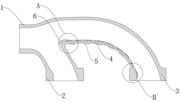
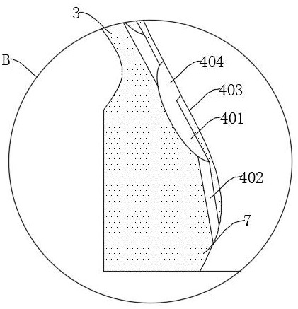
[0046] The present invention provides such Figure 1-5 The shown exhaust pipe for improving the efficiency of the exhaust system includes a main exhaust pipe 1, and the end of the main exhaust pipe 1 is communicated with a first auxiliary exhaust pipe 2 and a second auxiliary exhaust pipe 3 in a bifurcated form , the position where the first auxiliary exhaust pipe 2 communicates with the second auxiliary exhaust pipe 3 forms the corner 6 of the first turning a...


PUM


Abstract

The invention discloses an exhaust pipe capable of improving the efficiency of an exhaust system, and relates to the field of exhaust pipes, the exhaust pipe comprises an exhaust main pipe, and the end part of the exhaust main pipe is communicated with a first exhaust auxiliary pipe and a second exhaust auxiliary pipe which are bifurcated; the inner wall of the second auxiliary exhaust pipe is provided with a low-pressure suction area for draining and discharging gas at the gas outlet of the main exhaust pipe to the second gas outlet, and when the gas discharged from the main exhaust pipe is conveyed into the first auxiliary exhaust pipe and the second auxiliary exhaust pipe, part of the gas enters the first auxiliary exhaust pipe to be discharged; a low-pressure suction area is arranged on the inner wall of the lower end of the second auxiliary exhaust pipe, and the gas at the gas outlet of the main exhaust pipe can be sucked into the second auxiliary exhaust pipe, so that the phenomenon that a large amount of gas enters the first auxiliary exhaust pipe is avoided; and the low-pressure suction area has the effect of reducing the weakness degree when the gas is conveyed.

Description

technical field [0001] The invention relates to the field of exhaust pipes, in particular to an exhaust pipe for improving the efficiency of an exhaust system. Background technique [0002] The exhaust pipe is mainly used to discharge gas. The turning position of the exhaust pipe in the prior art is arranged in the form of an elbow. Because the structure of the elbow produces a diffused structure in some areas, flow separation occurs. After flow separation, the flow loss will increase and the flow velocity will be reduced. Affect the exhaust efficiency, especially when there are two bifurcated pipes at the end of a main exhaust pipe, due to the natural exhaust principle that the gas in the high pressure area flows to the low pressure area, the intake end of the main exhaust port here is the high pressure area, The end of the gas outlet is the low-pressure area. The gas outlet near the main exhaust pipe emits more gas, and the gas outlet farther from the main exhaust pipe em...

Claims


Application Information

Patent Timeline
Patent Type & Authority Applications(China)
IPC IPC(8): F16L41/02F15D1/04F15D1/06
CPCF16L41/02F15D1/04F15D1/06Y02T10/12
Inventor 王新校孙楠楠王德成周海磊栾军山陈彦波
Owner WEICHAI POWER CO LTD
Why Eureka
Try Eureka