
Railway energy route regulation and control method based on photovoltaic energy storage system

A photovoltaic energy storage and energy storage system technology, applied in the field of electrified railways, can solve problems such as strict requirements on the rated capacity and tolerance level of power electronic devices, inability to fully utilize railway energy routers, and lack of local fault tolerance in the system. Reduce performance requirements, improve fault tolerance, and improve the effect of negative sequence

Pending Publication Date: 2022-04-15
SOUTHWEST JIAOTONG UNIV
View PDF0 Cites 0 Cited by
  • Summary
  • Abstract
  • Description
  • Claims
  • Application Information

AI Technical Summary

Problems solved by technology

However, the current research mainly focuses on the centralized photovoltaic energy storage back-to-back converter system. The existing system has a large capacity and has strict requirements on the rated capacity and tolerance level of the power electronic devices inside the system; and this system does not With local fault tolerance, if some components in the external equipment are abnormal or fail, the overall equipment needs to be cut out of the running state
It can be seen that the existing technology cannot give full play to the function of the railway energy router, and the centralized photovoltaic modules lead to low utilization of photovoltaic systems

Method used

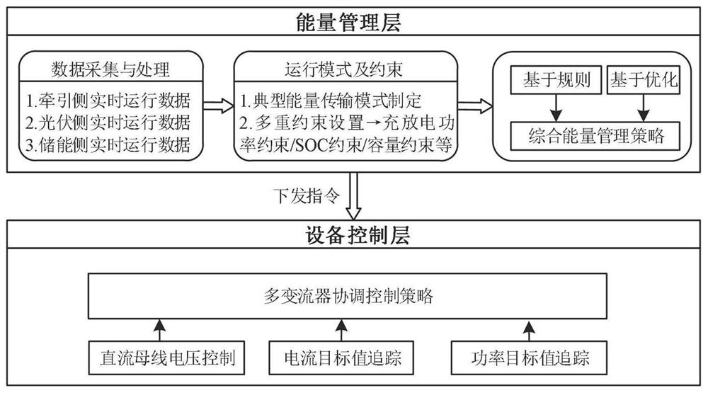
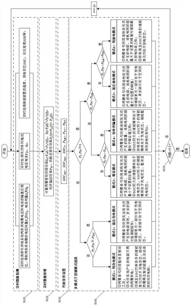

Image

  • Railway energy route regulation and control method based on photovoltaic energy storage system
  • Railway energy route regulation and control method based on photovoltaic energy storage system
  • Railway energy route regulation and control method based on photovoltaic energy storage system

Examples


Embodiment Construction

[0040] In order to make the purpose, technical solution and advantages of the present invention clearer, the present invention will be further elaborated below in conjunction with the accompanying drawings.

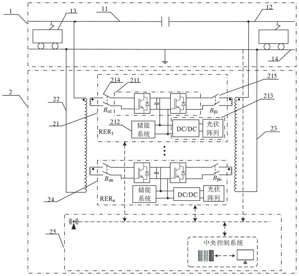
[0041] In this embodiment, the present invention proposes a photovoltaic energy storage system-based railway energy routing control method, which is applied to a photovoltaic energy storage system-based railway energy routing system. The photovoltaic energy storage system-based railway energy routing system is connected to the traction Network, the railway energy routing system based on the photovoltaic energy storage system includes multiple photovoltaic energy storage railway energy router subsystems, and the photovoltaic energy storage railway energy router subsystem includes back-to-back converters and photovoltaic energy storage systems.

[0042] Such as image 3 As shown, the railway energy routing system 2 based on photovoltaic energy storage system includes severa...


PUM


Abstract

The invention discloses a railway energy route regulation and control method based on a photovoltaic energy storage system, and the method comprises an energy management layer which is used for the comprehensive energy management of a whole system; based on the real-time operation data, switching the current operation mode of the renewable energy railway energy routing system, and issuing the calculated compensation current and / or power instructions of the back-to-back converter and the energy storage system in each subsystem to the equipment control layer; and the equipment control layer is used for coordinated control of the back-to-back converter, the energy storage system and the photovoltaic system in each subsystem, and the control target is to dynamically track the given compensation current and / or power instruction while realizing the stability of the intermediate DC bus voltage. Regenerative braking energy of the train can be effectively recycled, photovoltaic generated electric quantity is consumed, and the electric energy quality problem of a traction power supply system is solved; meanwhile, the fault-tolerant capability is realized; the tolerance requirement on internal power electronic devices in a high-voltage and high-capacity environment can be relieved; the system utilization rate is effectively improved.

Description

technical field [0001] The invention belongs to the technical field of electrified railways, in particular to a method for controlling railway energy routing based on a photovoltaic energy storage system. Background technique [0002] With the rapid development of electrified railways in my country, the annual power consumption of railways is as high as 90 billion kWh, which is equivalent to 36 billion kilograms of standard coal per year, and the emissions of carbon dioxide, sulfur dioxide and nitrogen oxides are huge; in order to achieve "carbon peak", With the vision of "carbon neutrality", scholars at home and abroad are actively promoting new power supply models. Photovoltaic power generation has become a hot spot that people pay attention to because of its advantages such as cleanness, no pollution, no noise, and large scale. [0003] The existing technology proposes a new power supply mode in which a photovoltaic power generation system and an energy storage system are...

Claims


Application Information

Patent Timeline
IPC IPC(8): H02J3/00H02J3/06H02J3/28H02J1/00H02J1/14H02J13/00B60M3/00
CPCH02J3/0073H02J3/06H02J3/28H02J1/00H02J1/14H02J13/00001B60M3/00H02J2203/10H02J2300/24Y02E70/30
Inventor 戴朝华廉静如
Owner SOUTHWEST JIAOTONG UNIV
Learn More