
Battery assembly of CTP configuration, electric vehicle and design method

A battery assembly and configuration technology, applied in the automotive field, can solve problems such as the inability to achieve integration and the complexity of battery components

Pending Publication Date: 2022-04-15
CHINA FIRST AUTOMOBILE
View PDF8 Cites 2 Cited by
  • Summary
  • Abstract
  • Description
  • Claims
  • Application Information

AI Technical Summary

Problems solved by technology

[0006] The invention provides a CTP configuration battery assembly, an electric vehicle and a design method thereof. The battery unit is laid on its side and the water-cooled plate is fixedly arranged to realize the integration of the water-cooled plate and the side plate of the box body, and the water-cooled plate assembly 3 and The flow channel structure inside the box rear end plate 6 and the box front end plate 4 forms a closed thermal management coolant flow channel circuit, and the external connection water pipe joint 7 can realize the separation of dry and wet inside the battery pack. The design of no water pipe improves the assembly performance , reducing the risk of leakage caused by water pipe conversion joints, and solving the problem that the existing battery components are complicated and cannot be integrated

Method used


Image

  • Battery assembly of CTP configuration, electric vehicle and design method
  • Battery assembly of CTP configuration, electric vehicle and design method
  • Battery assembly of CTP configuration, electric vehicle and design method

Examples


Embodiment 1

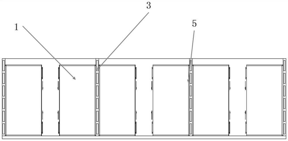
[0048] refer to figure 1 and figure 2 , the present embodiment provides a CTP-shaped battery assembly, including a battery case and a battery pack disposed in the battery case.

[0049] The battery pack includes a battery module 1 in a CTP configuration, a box beam 2 , a water cooling plate 3 , a box front plate 4 , a thermally conductive structural adhesive 5 , a box rear end plate 6 and a water pipe joint 7 .

[0050] The battery box includes a box front end plate 4, a box rear end plate 6, a box bottom plate and a box side plate.

[0051] The battery module 1 in the CTP configuration is arranged lying on its side, and the bottom is fixed on the water-cooled plate 3 through the heat-conducting structural adhesive 5 to realize the fixed installation of the battery module 1 in the CTP configuration. The adhesive bonding strength of the thermally conductive structural adhesive 5 is ≥4MPa and the thermal conductivity is ≥0.2W / m*k), which can not only ensure the heat conductio...

Embodiment 2

[0063] This embodiment provides an electric vehicle, including a CTP-configured battery assembly in Embodiment 1. The electric vehicle adopts a battery assembly with a CTP configuration in the embodiment. The battery unit is laid on its side and the water-cooled plate is fixedly arranged to realize the integration of the water-cooled plate and the side plate of the box body. In this case, the upper case of the battery will not be damaged, effectively delaying thermal runaway, and the water-cooled plate assembly 3 forms a closed thermal management coolant flow path circuit with the flow channel structure inside the rear end plate 6 of the case and the front end plate 4 of the case. The external connection of the water pipe joint 7 can realize the separation of dry and wet inside the battery pack. The design of no water pipe improves the assembly performance, reduces the risk of leakage caused by the water pipe conversion joint, and solves the problem that the existing battery co...

Embodiment 3

[0065] A design method for a CTP-configured battery assembly, for designing a CTP-configured battery assembly, comprising the following steps:

[0066] Step 1. Take the layout boundary and performance requirements of the battery pack as design input;

[0067] Step 2. Determine the number of battery modules according to the layout boundary of the battery pack and the performance requirements, and further confirm the number of battery modules 1 in the CTP configuration;

[0068] Step 3. Determine the number of water-cooled plates 3 based on the number of battery modules 1 in CTP configuration. Among them, the water-cooled plates integrated with the side panels of the box are arranged with one battery module 1 in CTP configuration, and the water-cooled plates 3 in the middle are arranged with two A battery module 1 in a CTP configuration;

[0069] Step 4. Determine the position and thickness of the box beam 2 by the number of battery modules 1 in the CTP configuration, the numbe...


PUM

PropertyMeasurementUnit
Bond strengthaaaaaaaaaa
Thermal conductivityaaaaaaaaaa

Abstract

The invention relates to a battery assembly of a CTP configuration, an electric vehicle and a design method. Comprising a battery box body and a battery pack arranged in the battery box body, the battery pack comprises a battery module with a CTP structure, a box body cross beam, a water cooling plate, a box body front end plate, a heat-conducting structural adhesive, a box body rear end plate and a water pipe joint; the battery box body comprises a box body front end plate, a box body rear end plate, a box body bottom plate and box body side plates; the battery module is fixed on the water cooling plate; the battery modules in the length direction of the battery box body are separated by box body cross beams; the battery modules in the width direction of the battery box body are separated by a water cooling plate; the water pipe connector is connected with a runner of the water cooling plate. Integration of the water cooling plate and the box body side plate can be achieved, the water cooling plate assembly, the box body rear end plate and the box body front end plate form a closed heat management cooling liquid flow channel loop, the water pipe connector is externally connected, dry-wet separation and water-pipe-free design in the battery pack can be achieved, the assembly performance is improved, and the assembly efficiency is improved. And the leakage risk caused by the water pipe adapter is reduced.

Description

technical field [0001] The invention relates to the technical field of automobiles, in particular to a CTP configuration battery assembly, an electric vehicle and a design method. Background technique [0002] At present, the development prospects of new energy vehicles are very broad, but with the development of technology, various safety issues of new energy vehicles frequently arise. As a key core component of new energy vehicles, the integration of power batteries has always been a difficult problem in the industry. At present, the components of lithium-ion batteries are complex and various, and it is impossible to realize integrated design. [0003] In response to the above problems, the application with the publication number CN209389112U provides a battery pack, which includes more than two battery modules; each battery module includes a frame and a plurality of battery cells accommodated in the frame; adjacent A sleeve is fixedly arranged between the frames; the sl...

Claims


Application Information

Patent Timeline
IPC IPC(8): H01M50/244H01M50/258H01M10/613H01M10/625H01M10/653H01M10/6555H01M10/6554H01M10/6556H01M10/6557H01M10/6568B60L58/26
CPCH01M50/244H01M50/258H01M10/613H01M10/625H01M10/653H01M10/6555H01M10/6554H01M10/6556H01M10/6557H01M10/6568B60L58/26Y02E60/10Y02T10/70
Inventor 卢军孙焕丽于长虹李黎黎许立超岳振东刘鹏耿宇明
Owner CHINA FIRST AUTOMOBILE
Learn More