A method and device for multi-point unlabeled differential super-resolution imaging

A super-resolution imaging and labeling technology, applied in the field of optical engineering, can solve the problems of complex system structure, the detector cannot be sold separately, and the single-frame exposure speed of the area array detector cannot be compared with that of the single-photon detector, etc., to improve imaging. The effect of efficiency

Active Publication Date: 2022-07-08
ZHEJIANG LAB +1
View PDF7 Cites 0 Cited by
  • Summary
  • Abstract
  • Description
  • Claims
  • Application Information

AI Technical Summary

Problems solved by technology

In the differential imaging technique reported so far, up to 19 single photon counters are used, which is limited by the system cost
The relevant confocal equipment of Zeiss can realize the subdivision of 37 detectors, but the detectors cannot be sold separately, and are currently only used for common confocal imaging
More subdivisions can be achieved by using an area array detector, but because the single-frame exposure speed of the area array detector cannot be compared with that of the single photon detector, the imaging speed is greatly reduced
[0004] In addition, traditional differential imaging needs to scan the sample twice with a hollow focal spot and a solid focal spot, and the imaging speed is twice as slow as confocal under the same conditions
Some researchers use dual focal points (hollow focal spot and solid focal spot) to scan in parallel and detect at the same time to achieve differential imaging, but the system structure is relatively complicated and two single photon counters are required

Method used


Image

  • A method and device for multi-point unlabeled differential super-resolution imaging
  • A method and device for multi-point unlabeled differential super-resolution imaging
  • A method and device for multi-point unlabeled differential super-resolution imaging

Examples


Embodiment Construction

[0031] The present invention will be further described below in conjunction with the accompanying drawings.

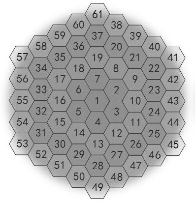
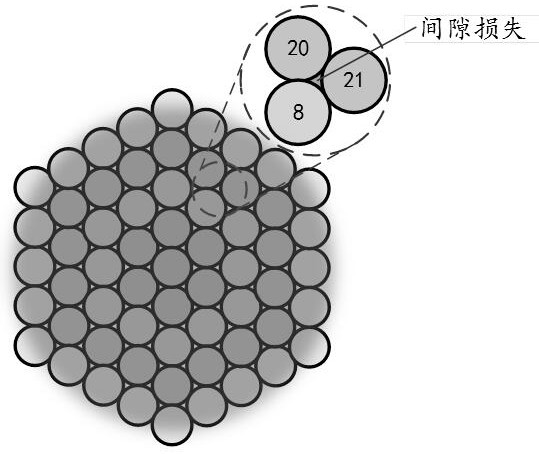
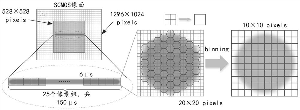
[0032] Airy disk subdivision is a process in which parallel detectors are used to subdivide the detected Airy disks and then perform image reorganization. like Figure 1a As shown, ideally, the higher the number of parallel detectors, the better the imaging quality. Taking 61 detectors covering one Airy disk as an example, then finally 61 images will be obtained at the same time, and then one frame of image will be obtained after the image is translated and recombined. Although this method does not break the diffraction limit, it greatly increases the proportion of high-frequency information, and thus achieves a resolution and signal-to-noise ratio that surpasses conventional confocal imaging. While the more subdivisions, the better the imaging quality, the higher the number of detectors required. In practice, if a single photon counter is used as a detector, on the ...


PUM


Abstract

The invention discloses a multi-focus non-marking differential super-resolution imaging method and device based on an area array detector and Airy disk subdivision. The beams of light are modulated by the phase masks loaded on the left and right half-screens of the SLM, respectively, and the two beams are solid beams and hollow beams; then the solid beams and hollow beams are combined, and the combined beams are divided into first The sub-beam and the second sub-beam, including solid beam and hollow beam respectively, are incident on the scanning galvanometer module at a certain angle, and are focused by the objective lens to form the first focal spot combination and the second focal spot combination, thereby forming a Four focal spots. Based on the method of transforming the time domain into the space domain, using the area array detector instead of the single-point detector, at a relatively low cost, the Airy disk 4 can be subdivided into more than 40 detectors. At the same time, multi-focus excitation is adopted to further improve the imaging efficiency of the system.

Description

technical field [0001] The invention belongs to the field of optical engineering, in particular to a multi-point non-marking differential super-resolution imaging method and device based on a surface array detector and Airy disk subdivision. Background technique [0002] Optical super-resolution imaging has the great advantages of being non-destructive, intuitive, and high-resolution. In the past two decades, a variety of super-resolution microscopes have been proposed and developed. These techniques can be divided into two categories: ① fluorescent labeling super-resolution microscopy, including emission depletion microscopy, localization microscopy, structured illumination microscopy, etc.; ② label-free super-resolution microscopy. Label-free microscopy can visually observe the structure of samples without the limitation of dyes, but compared with fluorescence imaging technology, label-free microscopy has developed relatively slowly in super-resolution capability. At pres...

Claims


Application Information

Patent Timeline
Patent Type & Authority Patents(China)
IPC IPC(8): G02B27/58G02B21/00G01N21/84
Inventor 朱大钊匡翠方张智敏刘秋兰杨臻垚马程鹏刘锡徐良丁晨良刘旭
Owner ZHEJIANG LAB
Why Eureka
Try Eureka