Image encoder and decoder using undirectional prediction
What is Al technical title?
Al technical title is built by PatSnap Al team. It summarizes the technical point description of the patent document.
a technology of encoder and decoder, applied in the field of image encoding and decoding techniques, can solve the problem of adding unidirectional flag information, and achieve the effect of reducing the capacity of the encoded image and improving the encoded image efficiency
Active Publication Date: 2014-10-21
ELECTRONICS & TELECOMM RES INST +2
View PDF9 Cites 19 Cited by
Summary
Abstract
Description
Claims
Application Information
AI Technical Summary
This helps you quickly interpret patents by identifying the three key elements:
Problems solved by technology
Method used
Benefits of technology
[0010]An aspect of the present invention provides an image encoder and decoder using unidirectional prediction that may improve an encoding efficiency of an image.
[0011]An aspect of the present invention provides an image encoder and decoder using unidirectional prediction that may effectively encode an image, thereby reducing a capacity of the encoded image.Technical Solutions
[0015]According to the present invention, an encoding efficiency of an image may be improved.
[0016]According to the present invention, an image may be effectively encoded, thereby reducing a capacity of the encoded image.
Problems solved by technology
However, in the conventional moving picture compression standard, a case where the intra prediction mode and an practical encoding mode are identical to each other in the intra 4×4 encoding mode may be consecutively generated, and thereby unidirectional flag information may be required to be added to reduce a number of bits to be encoded.
Method used
Image
Click on the blue label to locate the original text in one second.
Reading with bidirectional positioning of images and text.
Examples
Embodiment Construction
[0031]Reference will now be made in detail to embodiments of the present invention, examples of which are illustrated in the accompanying drawings, wherein like reference numerals refer to the like elements throughout. The embodiments are described below in order to explain the present invention by referring to the figures.
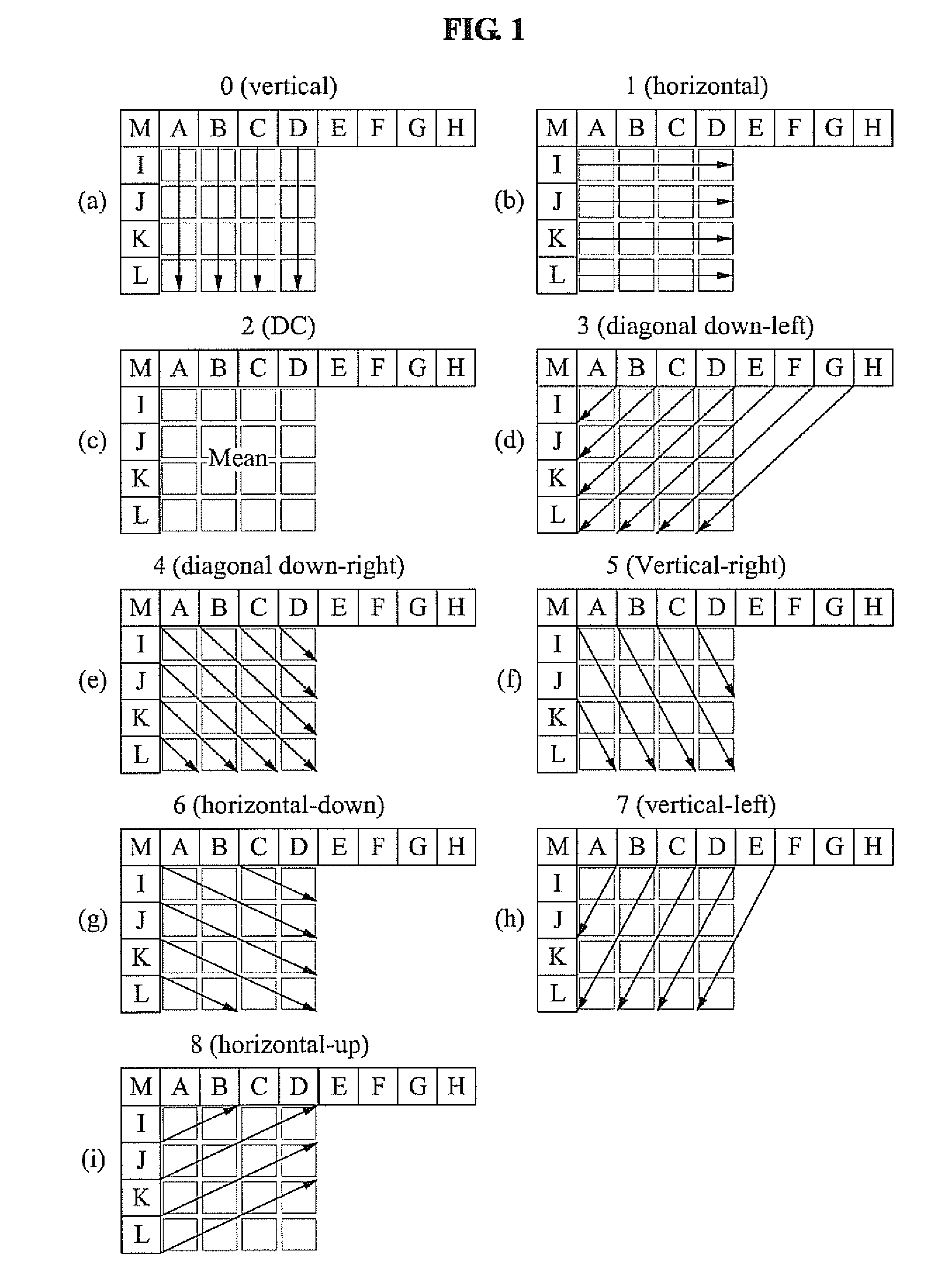
[0032]FIG. 1 illustrates various examples of an intra prediction mode. A macro block intended to be encoded may be divided into at least one sub-block. An image encoder according to exemplary embodiments may calculate a difference between a pixel value of each sub-block and a pixel value of a reference pixel to generate a difference image, and encode the generated difference image.
[0033]When a value of the difference image is small, a relatively greater number of bits may be assigned to data within a small range, and thereby an image may be more accurately encoded to reduce a distortion. Depending on characteristics of an image included in each sub-block, a locati...
PUM
Abstract
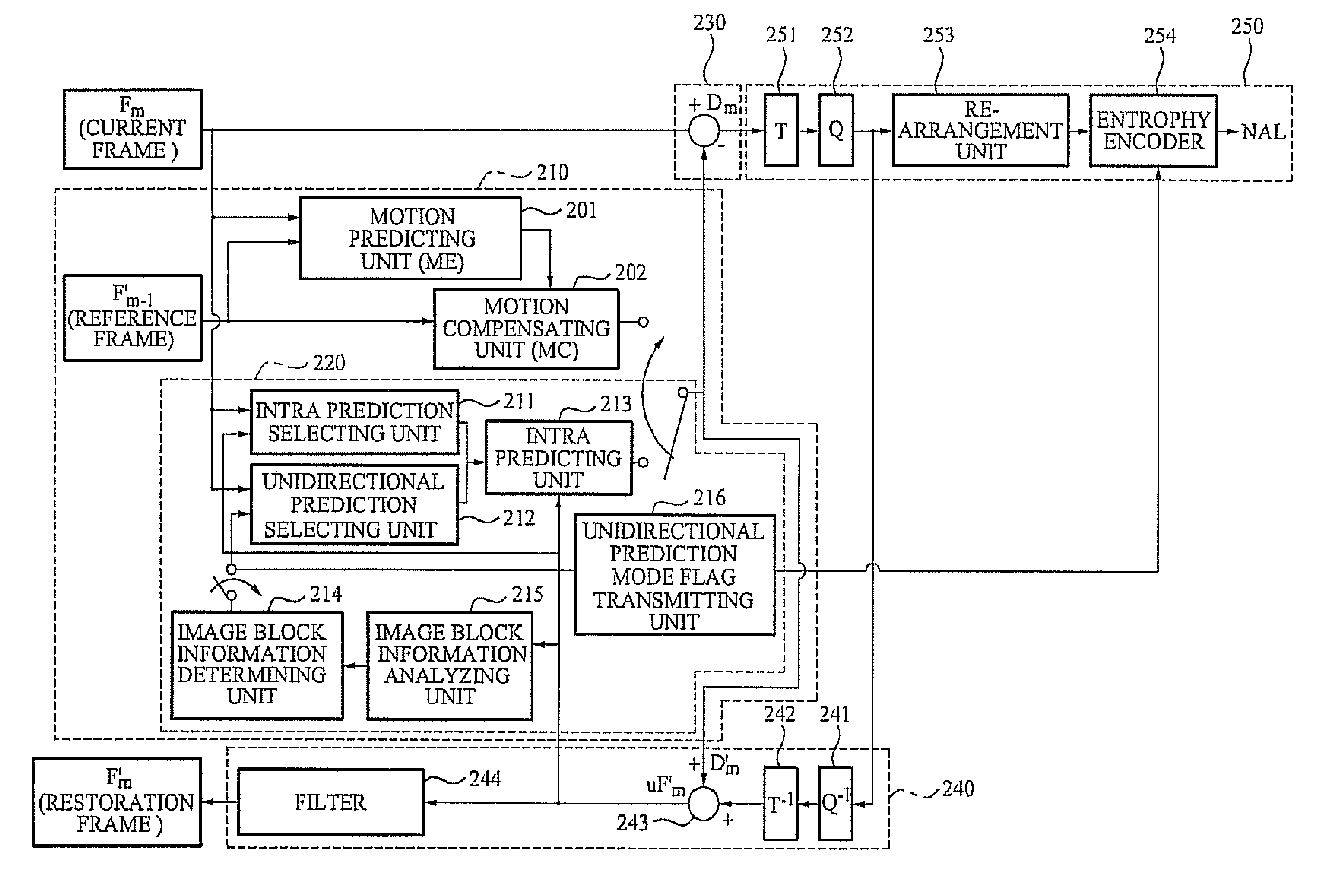
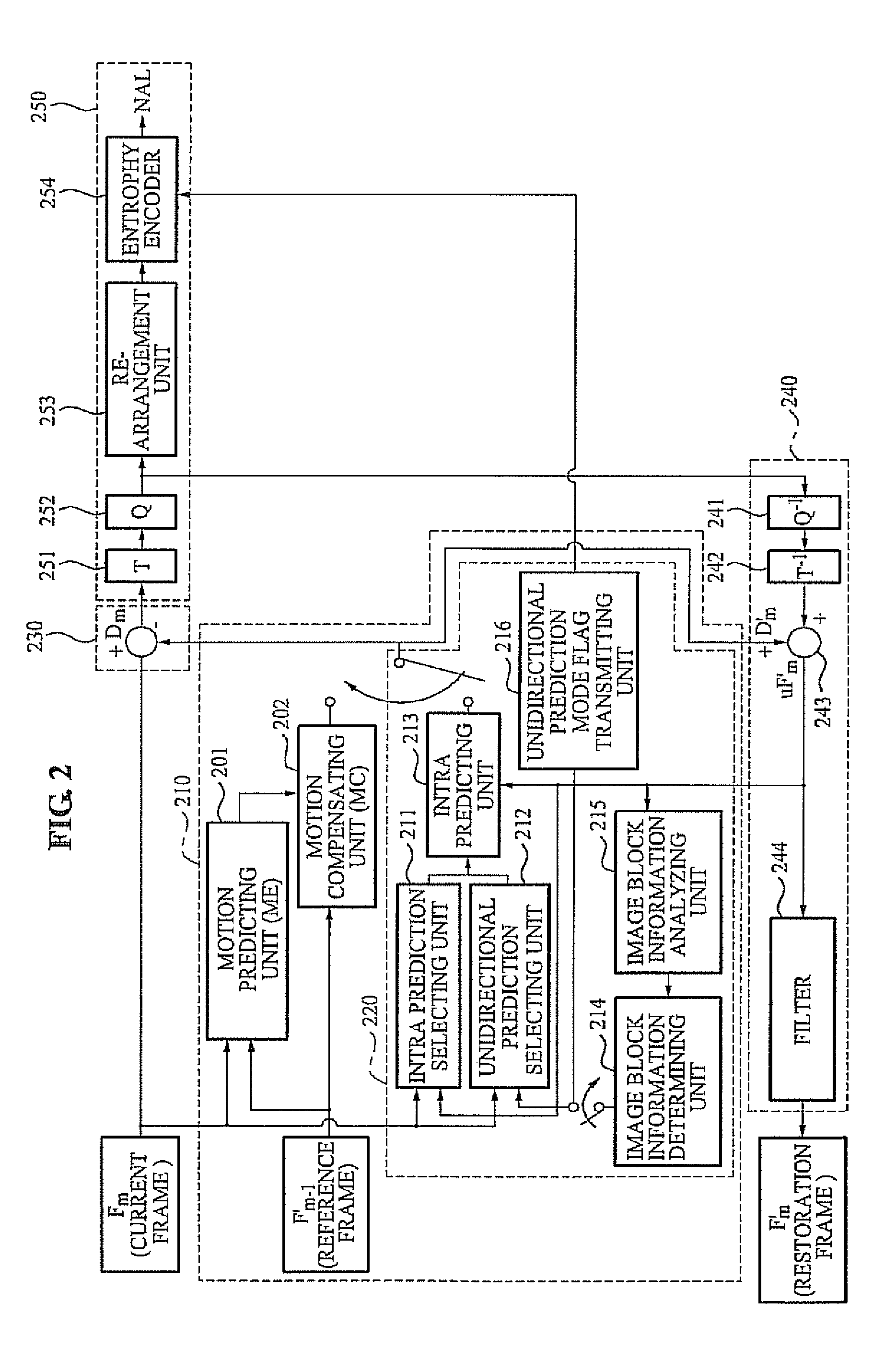
The present invention relates to an image encoding and decoding technique, and more particularly, to an image encoder and decoder using unidirectional prediction. The image encoder includes a dividing unit to divide a macro block into a plurality of sub-blocks, a unidirectional application determining unit to determine whether an identical prediction mode is applied to each of the plurality of sub-blocks, and a prediction mode determining unit to determine a prediction mode with respect to each of the plurality of sub-blocks based on a determined result of the unidirectional application determining unit.
Description
[0001]This application is a continuation of U.S. patent application Ser. No. 13 / 129,570 filed on May 16, 2011, now U.S. Pat. No. 8,363,965 which a national stage application of PCT / KR2009 / 005647 filed on Oct. 1, 2008 and claims priority of Korean patent application numbers 10-2008-0096658, 10-2009-0001240, and 10-2009-0093128 filed on Oct. 1, 2008, Jan. 7, 2009, and Sep. 30, 2009, respectively. The disclosure of each of the foregoing applications is incorporated herein by reference in its entirety.TECHNICAL FIELD[0002]The present invention relates to an image encoding and decoding technique, and more particularly, to an image encoder and decoder using unidirectional prediction.BACKGROUND ART[0003]In video compression technologies such as Moving Picture Experts Group (MPEG) 4 and H.264 standards, various prediction schemes may be used to improve a compression effect. Of these, an intra prediction encoding scheme may be generally used.[0004]An intra prediction mode may generate a pred...
Claims
Application Information
Patent Timeline
Application Date:The date an application was filed.
Publication Date:The date a patent or application was officially published.
First Publication Date:The earliest publication date of a patent with the same application number.
Issue Date:Publication date of the patent grant document.
PCT Entry Date:The Entry date of PCT National Phase.
Estimated Expiry Date:The statutory expiry date of a patent right according to the Patent Law, and it is the longest term of protection that the patent right can achieve without the termination of the patent right due to other reasons(Term extension factor has been taken into account ).
Invalid Date:Actual expiry date is based on effective date or publication date of legal transaction data of invalid patent.