Flying probe testing machine and testing shaft polarity distribution method thereof

A technology of flying probe testing machine and distribution method, which is applied in the field of flying probe testing, can solve problems such as property loss and easy collision of test axes, and achieve the effect of avoiding interference and collision

Active Publication Date: 2022-04-15
苏州格拉尼视觉科技有限公司
View PDF12 Cites 0 Cited by
  • Summary
  • Abstract
  • Description
  • Claims
  • Application Information

AI Technical Summary

Problems solved by technology

However, in the prior art, due to the spatial distribution of the test points on the PCB board, the test axis is prone to collision during high-speed operation. Once a collision occurs, huge property losses will occur

Method used


Image

  • Flying probe testing machine and testing shaft polarity distribution method thereof
  • Flying probe testing machine and testing shaft polarity distribution method thereof

Examples


Embodiment Construction

[0028] The specific embodiments of the present invention will be described in detail below in conjunction with the accompanying drawings, but it should be understood that the protection scope of the present invention is not limited by the specific embodiments.

[0029] Unless expressly stated otherwise, throughout the specification and claims, the term "comprise" or variations thereof such as "includes" or "includes" and the like will be understood to include the stated elements or constituents, and not Other elements or other components are not excluded.

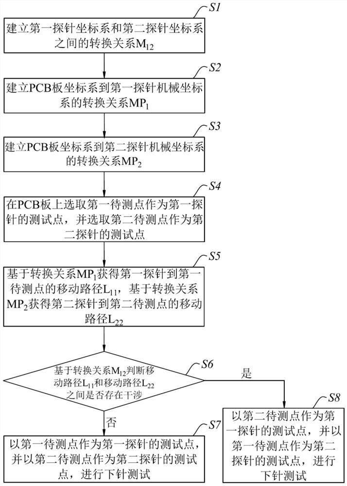
[0030] Please refer to figure 1 As shown, it is a flow chart of the testing axis polarity assignment method of the flying probe testing machine in one embodiment of the present invention. The test method can be used for the test of the PCB board by the flying probe tester. The flying probe tester includes a first test axis and a second test axis. The first test axis is provided with a first probe and a first camera, and the ...


PUM


Abstract

The invention discloses a flying probe testing machine and a testing shaft polarity distribution method thereof. The method comprises the following steps: establishing a conversion relation M12 between a first probe coordinate system and a second probe coordinate system, a moving path L11 from a first probe to a first to-be-measured point, and a moving path L22 from a second probe to a second to-be-measured point; whether interference exists between the moving path L11 and the moving path L22 or not is judged based on the conversion relation M12; and if interference exists between the moving path L11 and the moving path L22, taking the second to-be-tested point as a test point of the first probe, and taking the first to-be-tested point as a test point of the second probe, and carrying out probe placement test. According to the flying probe testing machine and the testing shaft polarity distribution method thereof, whether interference collision occurs in the testing shaft corresponding to the probe in the testing process can be judged according to the position and the corresponding relation between the testing point on the PCB and the corresponding probe, and the polarity of the testing shaft is distributed according to the judgment result, so that the testing accuracy is improved. Therefore, interference and collision of the test shaft during a lower needle test are avoided.

Description

technical field [0001] The invention relates to the technical field of flying probe testing, in particular to a flying probe testing machine and a test shaft polarity distribution method thereof. Background technique [0002] The PCB board flying probe test machine uses probes to replace the needle bed, and uses multiple motor-driven, fast-moving electrical probes to contact the pins of the device and perform automated testing. In the test process, the test axis is required to have the characteristics of high speed, high precision and wide test range. However, in the prior art, due to the problem of the spatial distribution of test points on the PCB, the test axis is prone to collision during high-speed operation. Once a collision occurs, huge property losses will occur. [0003] Therefore, in view of the above technical problems, it is necessary to provide a flying probe testing machine and a testing axis polarity distribution method thereof. Contents of the invention ...

Claims


Application Information

Patent Timeline
IPC IPC(8): G01R1/04
Inventor 朱春雷
Owner 苏州格拉尼视觉科技有限公司
Why Eureka
Try Eureka