A method to actively prevent interference collisions between alternate tool paths in digital manufacturing operations
An inter-operating and indirect technology, applied in the field of mechanical processing, can solve problems such as heavy workload, limited versatility, easy to forget, mistakes, etc., achieve the effect of reducing knowledge and ability requirements, realizing active safety, and avoiding interference and collision
- Summary
- Abstract
- Description
- Claims
- Application Information
AI Technical Summary
Problems solved by technology
Method used
Image
Examples
Embodiment 1
[0030] Embodiment 1. Taking the W518S one turntable one swing head five-axis digital milling machine as an example, the invention is further described in detail:
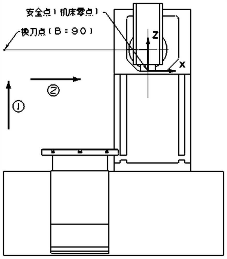
[0031] The zero point of the W518S machine tool is the positive limit point of the travel of the X, Y, and Z axes. It is located at the upper right corner of the rear of the machine tool. image 3 , attached Figure 4 shown. The coordinates of the safe point of the machine tool relative to the zero point of the machine tool are (0, 0, 0), the tool change point is on the left side of the machine tool, and the tool change is in the state of B=90°.
[0032] The NC program segment (FANUC 16M control system) for the machine tool to reach the safe point of the machine tool from the machining operation avoidance point is as follows:
[0033] The NC program segment from the machining operation avoidance point to the safe point during the non-tool change operation is:
[0034] G53 Z0;...Execute path ①, Z axis returns to t...
Embodiment 2
[0043] Embodiment 2, taking the UCP600 double turntable five-axis digital milling machine as an example, the invention is further described in detail:
[0044] The zero point of the UCP600 machine tool is the intersection point of A and C axes, and the safety point of the machine tool is set as the positive limit point of the travel of the Y and Z axes. Figure 5 , attached Figure 6 shown. The coordinates of the safe point of the machine tool relative to the zero point of the machine tool are (0, 300, 380), and the tool change point is near the point (0, 300, 300).
[0045] The NC program segment (HEIDENHAIN control system) for the machine tool to reach the safe point of the machine tool from the machining operation avoidance point is:
[0046] L Z380. F MAX M92... Execution path ①, Z axis returns to the safe point
[0047] L X0. Y300. F MAX M92...Execution path ②, X, Y axis return to safe point
[0048] By developing the special post-processing program for UCP600 machine...
Embodiment 3
[0049] Embodiment 3, taking the four-axis digital milling machine tool with dividing head of DMC1035V as an example, the invention is further described in detail:
[0050] The zero point of the DMC1035V machine tool is the positive limit point of the X, Y, and Z-axis travel, which is located at the upper right corner of the rear of the machine tool. The safety point of the machine tool is set as the negative limit point of the X-axis travel. The coordinates of the Y and Z axes are the same as the zero point coordinates of the machine tool. Figure 7 , attached Figure 8 shown. The coordinates of the safe point of the machine tool relative to the zero point of the machine tool are (-1035, 0, 0), and the tool change point is around 80mm below the safe point.
[0051] The NC program segment (SIEMENS 840D) for the machine tool to reach the safe point of the machine tool from the machining operation avoidance point is:
[0052] SUPA G0 Z-5. D0...Execution path ①, Z axis returns t...
PUM
 Abstract
Description
Claims
Application Information
 - R&D
- Intellectual Property
- Life Sciences
- Materials
- Tech Scout
- Unparalleled Data Quality
- Higher Quality Content
- 60% Fewer Hallucinations
Browse by: Latest US Patents, China's latest patents, Technical Efficacy Thesaurus, Application Domain, Technology Topic, Popular Technical Reports.
© 2025 PatSnap. All rights reserved.Legal|Privacy policy|Modern Slavery Act Transparency Statement|Sitemap|About US| Contact US: help@patsnap.com


