Rotary injection pump

A technology of rotating jet pump and pump body, applied in the direction of pump, pump element, non-variable-capacity pump, etc., can solve the problems of prone to cavitation, anti-overflow capability and poor hydraulic efficiency of impeller, so as to improve the overflow capability. , the effect of increasing the flow capacity and reducing the hydraulic loss

Pending Publication Date: 2022-04-15
黎成行
View PDF0 Cites 0 Cited by
  • Summary
  • Abstract
  • Description
  • Claims
  • Application Information

AI Technical Summary

Problems solved by technology

[0003] The existing rotary jet pumps have poor anti-overflow capability and impeller hydraulic efficiency when in use, and cavitation is prone to occur in large flow conditions. Therefore, a rotary jet pump is proposed

Method used


Image

  • Rotary injection pump
  • Rotary injection pump
  • Rotary injection pump

Examples


Embodiment Construction

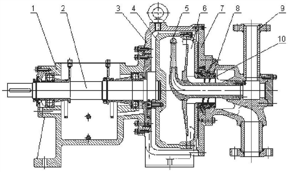
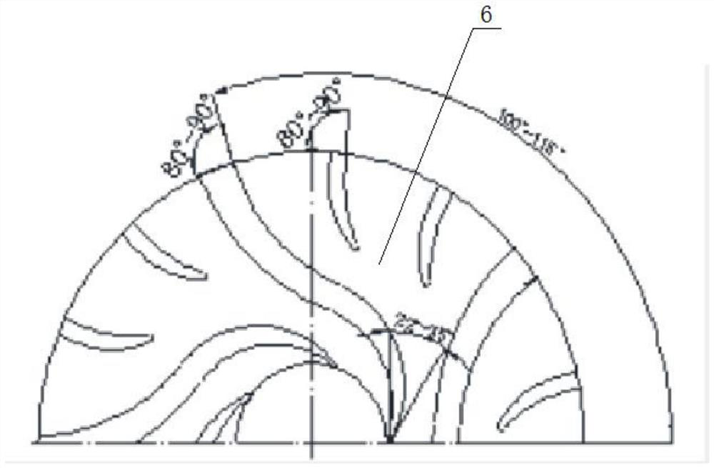
[0022] like Figure 1-3 As shown, a rotary jet pump includes a bearing housing 1, a main shaft 2 and a rotor chamber 4. A pump body 3 is installed behind the bearing housing 1, and a main shaft 2 runs through the middle of the inner side. The main shaft 2 is rotationally connected with the bearing housing 1 through a bearing group. One end of the main shaft is connected to the motor by a coupling, and the other end is connected to the rotor cavity 4 by a flange. The pump body 3 and the bearing box 1 are connected by bolts and precisely positioned by the seam to form a whole. Its feet are connected to the bearing box 1 The feet are adjusted to ensure the installation level of the pump. The rotor chamber 4 is arranged in the inner middle part of the pump body 3 and is fixedly connected with the main shaft 2. Its outer diameter is smaller than the inner diameter of the pump body 3, and the inner middle part of the rotor chamber 4 is equipped with a collecting pipe 5, and the righ...


PUM


Abstract

The rotary injection pump comprises a bearing box, a main shaft and a rotor cavity, the main shaft penetrates through the middle of the inner side of the bearing box, a pump body is installed behind the bearing box, and the rotor cavity is formed in the middle of the inner side of the pump body. According to the rotary jet pump, the inlet angle of the blade is 22-35 degrees, the outlet angle of the blade is 80-90 degrees, compared with a traditional radial equal-width linear blade, the flow area can be remarkably increased, the flow of the pump is improved, meanwhile, 1-3 short blades with the same outlet angle are arranged at the outlet of the impeller, the inlet angle of the short blades is determined according to the medium flowing rule, and the flow rate of the pump is increased. The hydraulic loss of the blade outlet section caused by flow separation and secondary backflow can be obviously reduced, and the hydraulic efficiency of the impeller is improved; in order to solve the cavitation problem of the rotary jet pump under the large-flow working condition, a shaft sleeve with an inner hole provided with induction blades is designed so as to increase the impeller inlet pressure and improve the anti-cavitation performance of the pump, and an inlet turning section of a collecting pipe is designed to be of a large arc structure so as to reduce flow separation and impact loss of the inlet section of the collecting pipe.

Description

technical field [0001] The invention relates to the technical field of rotary jet pumps, in particular to a rotary jet pump. Background technique [0002] Large-scale production devices in modern chemical, petrochemical, petroleum, metallurgy, carbon black and other industries all require low-flow, high-lift pumps to meet their process requirements. Traditionally, multi-stage pumps with complex structures, high costs, and difficult repairs are used. In the later imported large-scale devices, some of them were replaced by plunger pumps and high-speed pumps, but the outlet pressure of the former was unstable, and a supporting voltage stabilizing device was often required. The speed of the latter was mostly higher than 10,000 rpm, and some even reached 20,000 rpm. and higher operating risks. Therefore, a rotary jet pump with low rotating speed (3000-5000rpm), simple structure, safety, reliability, high efficiency and convenient maintenance has emerged. [0003] Existing rotar...

Claims


Application Information

Patent Timeline
Patent Type & Authority Applications(China)
IPC IPC(8): F04D29/18F04D29/04F04D29/66F04D29/40
Inventor 黎成行
Owner 黎成行
Why Eureka
Try Eureka