
Connection structure of cold-insulation superconducting cable shielding layer current lead and assembly method thereof

A shielding layer current and superconducting cable technology, applied in the usage of superconductor elements, superconducting devices, connections, etc., can solve the problems of large assembly space, affecting the structure and size of the terminal thermostat, etc., and achieve small assembly space and overall The effect of small size and optimized overall performance

Active Publication Date: 2012-05-23
北京云电英纳超导电力技术有限公司 +1
View PDF5 Cites 12 Cited by
  • Summary
  • Abstract
  • Description
  • Claims
  • Application Information

AI Technical Summary

Problems solved by technology

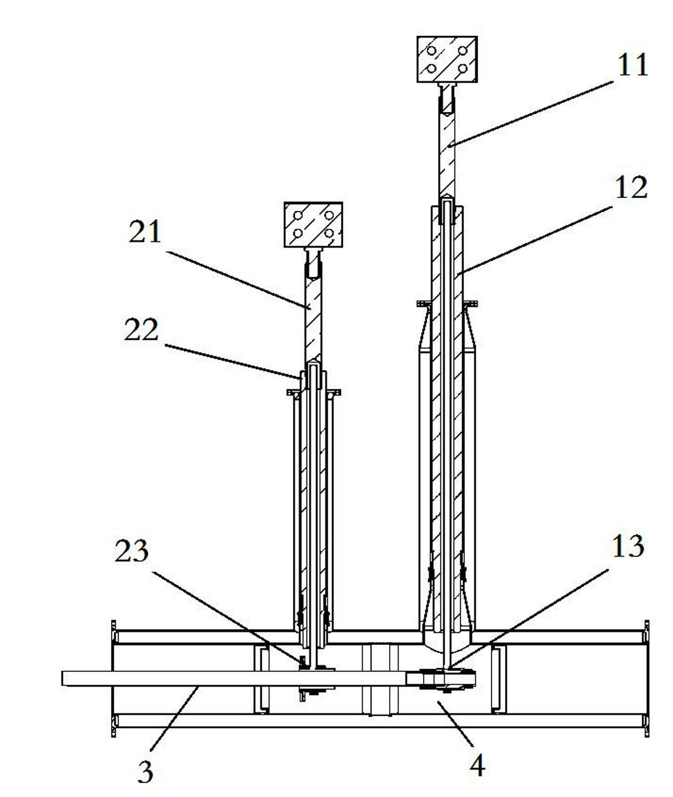
However, since the shielding layer is on the outside of the cable, and its axial length is smaller than that of the conductive layer, its current lead connector needs to be directly fixed and welded on the cable body instead of being fixed with the support tube
In addition, from the perspective of assembly, the shielding layer connector needs to be assembled or disassembled in the thermostat, which requires a larger assembly space than the conductive layer connector, which directly affects the structure and size of the terminal thermostat.

Method used


Image

  • Connection structure of cold-insulation superconducting cable shielding layer current lead and assembly method thereof
  • Connection structure of cold-insulation superconducting cable shielding layer current lead and assembly method thereof
  • Connection structure of cold-insulation superconducting cable shielding layer current lead and assembly method thereof

Examples


Embodiment Construction

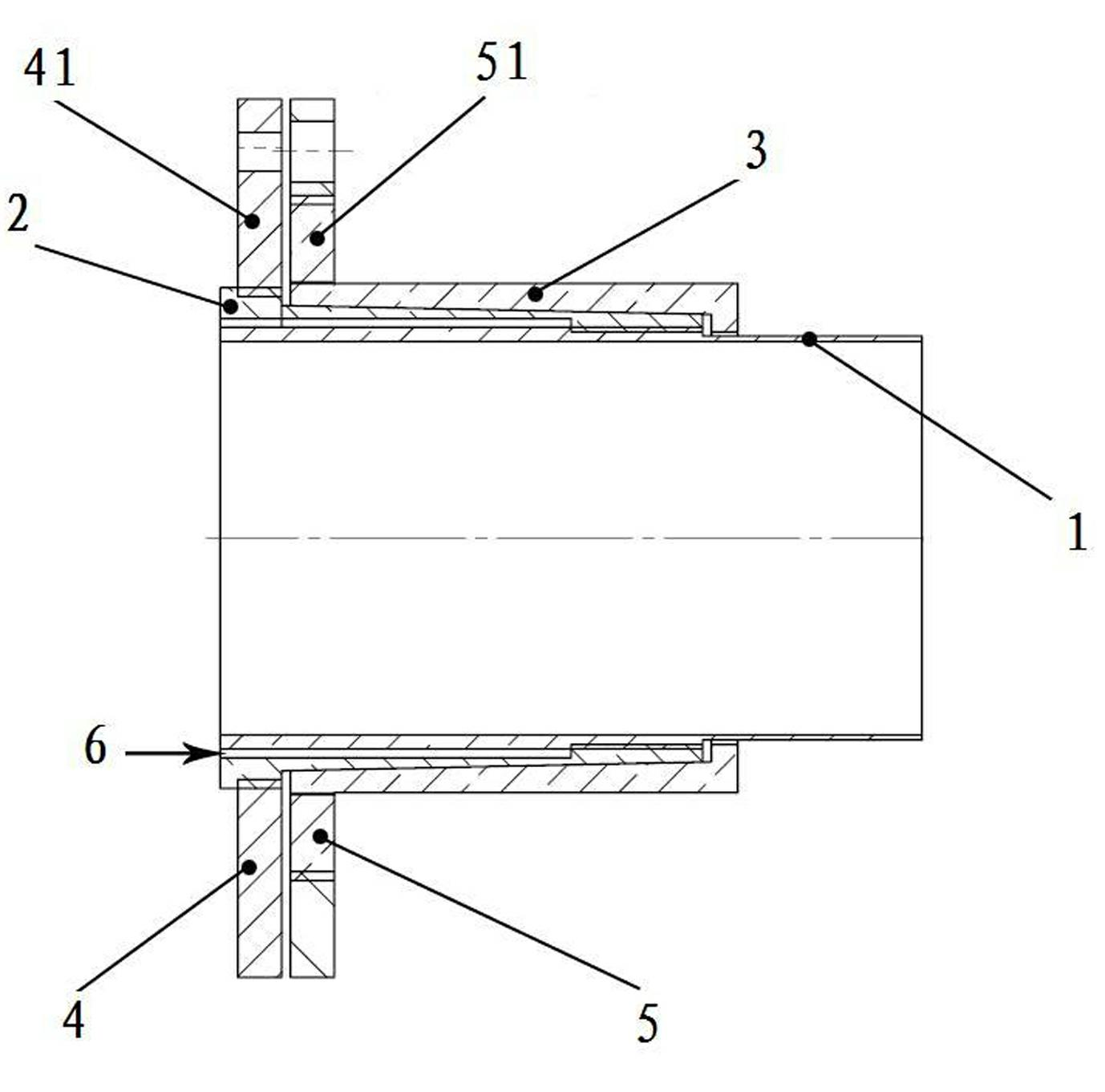
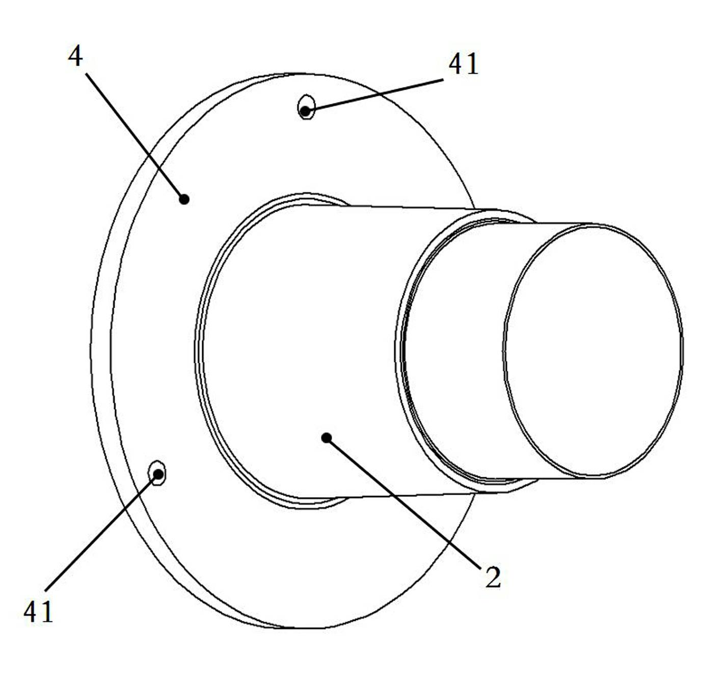
[0031] refer to figure 2 As shown, the connection structure of the current lead of the shielding layer of the cold insulated superconducting cable of the present invention includes an inner sleeve 1, a conductive cone 2, a conductive cone 3 and a set of fastening flanges 4,5.

[0032] The outer wall of the inner sleeve 1 is a three-stage structure of tapered contraction, and the first and second stages ( figure 2 In the shown embodiment, the right direction is defined as the front) and the outer wall is respectively provided with external threads for connecting the conductive cone female 3 and the conductive cone pipe.

[0033] The conductive tapered tube 2 is a tapered tube, and the configuration of its inner side wall matches the outer wall of the inner sleeve 1 at the rear two steps (see figure 2 shown in ), the inner front end of the conductive cone tube 2 has the same internal thread as the inner sleeve 1, and the inner diameter of the conductive cone tube 2 needs to ...


PUM


Abstract

The invention relates to a connection structure of a cold-insulation superconducting cable shielding layer current lead and an assembly method thereof. The connection structure comprises an inner sleeve, a conducting taper pipe, a conducting nut, a first fastening flange disc and a second fastening flange disc, wherein the outer wall of the inner sleeve is of a taper-contraction third-order type structure; the conducting taper pipe is a taper pipe, the structure of the inner side wall of the conducting taper pipe is matched with the outer wall of a relative section of the inner sleeve, and a welding cavity is formed between the inner side wall of the conducting taper pipe and the distal end outer wall of the inner sleeve; the length and the taper of the inner side wall of a parent sectionof the conducting nut are consistent with those of the outer side wall of the relative section of the conducting taper pipe; and the first fastening flange for being in threaded connection with the conducting taper pipe and the second fastening flange for being in threaded connection with the conducting nut are respective provided with a group of a screw hole and a through hole for fastening, andthe second fastening flange is further provided with a threaded hole for detaching. The invention further provides the assembly method of the connection structure to realize the connection of each components of the connection structure. The connection structure disclosed by the invention has the advantages of low contact resistance, strong through-current capability and convenience for detaching and assembling.

Description

technical field [0001] The invention belongs to the application field of superconducting electric power technology, and in particular relates to a connection structure and an assembly method of a current lead wire of a shielding layer of a cold-insulated superconducting cable. Background technique [0002] High temperature superconducting cable is a new type of power transmission carrier with small size, light weight, low loss and large transmission capacity, and it is one of the most important development directions of future power transmission technology. High-temperature superconducting cables can be divided into cold-insulated superconducting cables and heat-insulated superconducting cables according to the insulation structure. Among them, cold insulated superconducting cables have attracted much attention from the power industry and superconducting power application fields due to their good electromagnetic shielding effect, large transmission capacity, small heat loss,...

Claims


Application Information

Patent Timeline
IPC IPC(8): H01R4/68H01R43/00H01B12/14
CPCY02E40/645Y02E40/60
Inventor 洪辉字美荣李强秦继承王建中龚伟志罗曦任安林胡昌斌
Owner 北京云电英纳超导电力技术有限公司
Learn More