
Prefabricated assembly type building splicing plate and splicing method thereof

A prefabricated assembly and plate technology, applied in construction, building construction, etc., can solve the problems of bolt breakage, slowness, and cumbersome plate installation process, and achieve the effect of avoiding bolt breakage and increasing stability.

Pending Publication Date: 2022-04-15
CHINA SHANXI SIJIAN GRP
View PDF0 Cites 0 Cited by
  • Summary
  • Abstract
  • Description
  • Claims
  • Application Information

AI Technical Summary

Problems solved by technology

[0003] There are the following disadvantages in the installation process of prefabricated panels: 1. When the panels are spliced, because there is a certain gap between two adjacent panels, the process of panel installation is very cumbersome and slow, which affects the installation efficiency of the panels; 2. Panels When splicing, bolts are usually used to lock the bolts at the edge. Due to the heavy weight of the plates, the bolts will break during adjustment, which is not conducive to the rapid splicing of the plates.

Method used


Image

  • Prefabricated assembly type building splicing plate and splicing method thereof
  • Prefabricated assembly type building splicing plate and splicing method thereof
  • Prefabricated assembly type building splicing plate and splicing method thereof

Examples


Embodiment 1

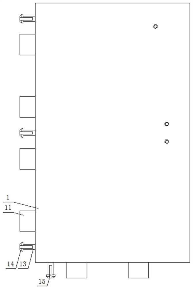
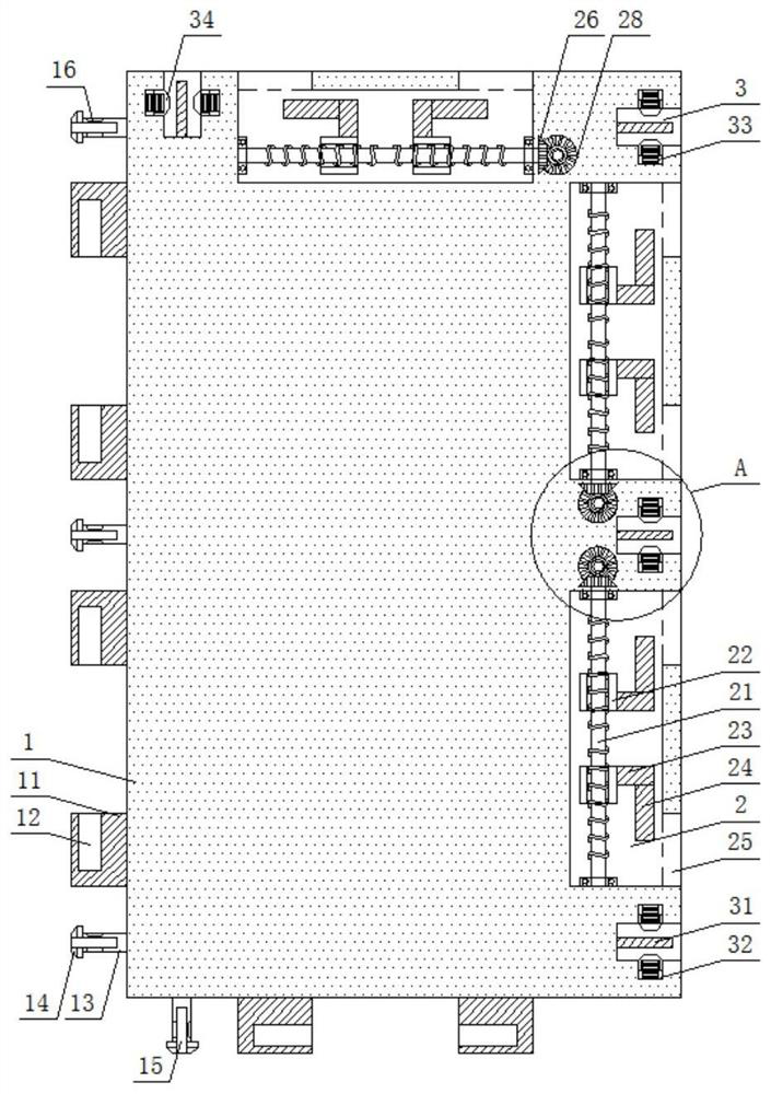
[0035] Embodiment 1: This embodiment provides prefabricated assembled building splicing panels, see Figure 1-7 Specifically, it includes a plate 1 and a limit assembly. The plate 1 is a rectangular plate placed vertically. There are rectangular cavities 2 in the middle of the top surface and the upper and lower sides of the right side of the plate 1. Each rectangular cavity 2 Two-way lead screws 21 placed in parallel are arranged inside, fixed bearings are arranged on the inner wall of the rectangular cavity 2 at positions corresponding to the two ends of the two-way lead screws 21, and the two ends of each two-way lead screw 21 are inserted into the In the corresponding fixed bearing, the thread teeth on the two sections of the two-way lead screw 21 are symmetrically arranged, and the two ends of each rectangular cavity 2 are provided with limiting through holes 25, and the bottom surface and the left side surface of the plate 1 have two upper and lower sides. A pair of limi...

Embodiment 2

[0038] Embodiment 2: In Embodiment 1, there is still the problem that the plates are simply snapped and locked through the limiting plate, which cannot guarantee the stability of the splicing of the plates. Therefore, on the basis of Embodiment 1, this embodiment also includes:

[0039] Specifically, see figure 2 with Figure 5 , one side of the top surface of the plate 1 and the middle and lower ends on the right side are provided with positioning grooves 3, and one side of the bottom surface of the plate 1 and the middle and lower ends on the left side are all provided with positioning plates 13, and each positioning plate 13 are all matched and inserted in the positioning groove 3 of another plate 1; the outer end of the positioning plate 13 is provided with a trapezoidal block 14, and the front and rear sides of the positioning plate 13 and the trapezoidal block 14 are all provided with a card slot 15, and the positioning groove 3 Blocks 31 are provided on the front and ...

Embodiment 3

[0041] Embodiment three: see Figure 8 , in this embodiment, the present invention also proposes a splicing method for prefabricated building splicing panels, including the following steps:

[0042] Step 1, when two boards 1 are spliced ​​together, the trapezoidal block 14 and the positioning plate 13 are inserted into the positioning groove 3 of the other one, the block 31 slides along the corresponding slot 15, and the trapezoidal block 14 drives the trapezoidal cap 34 along the Sliding inward along the spring groove 32, drives the spring 33 to be compressed and deformed;

[0043] Step 2, when the trapezoidal block 14 is completely pressed against the positioning groove 3, the tension of the spring 33 will drive the trapezoidal cap 34 to slide outward along the spring groove 32, and drive the top end of the trapezoidal cap 34 against the trapezoidal groove 16 , so that the trapezoidal cap 34 is pressed against the trapezoidal block 14;

[0044] Step 3, when the positioning...


PUM


Abstract

The prefabricated assembly type building splicing plate comprises a plate body and limiting assemblies, rectangular cavities are formed in the middle of the top face of the plate body and the upper side and the lower side of the right side face of the plate body correspondingly, a bidirectional lead screw is arranged in each rectangular cavity, and limiting through holes are formed in the two ends of each rectangular cavity correspondingly; a pair of limiting plates is arranged on the upper side and the lower side of the bottom face and the left side face of each plate, each limiting plate is installed in the limiting through hole of the other plate in a matched mode, and the two-way lead screw is connected with the limiting plate on the other plate through a limiting assembly; positioning grooves are formed in one side of the top face and the middle and lower ends of the right side face of each plate, positioning plates are arranged at one side of the bottom face and the middle and lower ends of the left side face of each plate, and each positioning plate is inserted into the positioning groove of the other plate in a matched mode. The problem that the plates are inconvenient to splice is solved, the whole plate is quickly spliced in an edge clamping and locking mode, and the stability of the plate during installation is effectively improved.

Description

technical field [0001] The invention relates to the technical field of assembled building boards, in particular to prefabricated assembled building splicing boards and a splicing method thereof. Background technique [0002] The prefabricated building refers to the transfer of a large number of on-site operations in the traditional construction method to the factory, where the building components and accessories are processed and manufactured, transported to the construction site, and assembled and installed on site through reliable connection methods. . [0003] There are the following disadvantages in the installation process of prefabricated panels: 1. When the panels are spliced, because there is a certain gap between two adjacent panels, the process of panel installation is very cumbersome and slow, which affects the installation efficiency of the panels; 2. Panels When splicing, bolts are usually used to lock the bolts at the edges. Due to the heavy weight of the plat...

Claims


Application Information

Patent Timeline
IPC IPC(8): E04B1/61
Inventor 卫芷郎龙龙刘宇鑫郭晓林高旭鹏王帅菅宇
Owner CHINA SHANXI SIJIAN GRP
Learn More