
Discharging air cooling device and air cooling method for cold pilger mill

A technology of cold-rolled pipe mill and air-cooling device, which is applied in metal rolling, metal rolling, metal processing equipment, etc., can solve problems such as easy deformation, achieve deformation prevention, improve quality and pass rate, and excellent cooling effect Effect

Active Publication Date: 2022-04-15
CHINA NAT HEAVY MACHINERY RES INSTCO
View PDF12 Cites 3 Cited by
  • Summary
  • Abstract
  • Description
  • Claims
  • Application Information

AI Technical Summary

Problems solved by technology

[0004] The purpose of the present invention is to solve the problem in the prior art that the pipes are easily deformed by the high temperature of cold rolling during the transmission process after cold rolling in the cold rolling mill, and propose a cold rolling mill with discharge air cooling device and air cooling method, the device can comprehensively and quickly cool down the pipes output from the cold rolling mill, prevent the deformation of the pipes during transportation after cold rolling, improve the quality and pass rate of the pipes processed by the cold rolling mill, and at the same time , the device also has the self-cleaning function of lubricating oil on the surface of the pipe, without manual operation, which reduces the labor intensity of the staff

Method used


Image

  • Discharging air cooling device and air cooling method for cold pilger mill
  • Discharging air cooling device and air cooling method for cold pilger mill

Examples


Embodiment 1

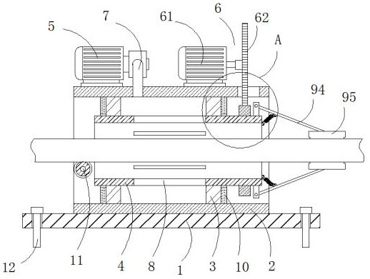
[0028] In order to overcome the problem in the prior art that the pipe is easily deformed by the high temperature of cold rolling during the transmission process after cold rolling in the cold rolling mill, the present invention provides such figure 1 A discharge air cooling device for a cold-rolled pipe mill is shown. The present invention can comprehensively and rapidly cool down the pipes output from the cold-rolled pipe mill, prevent the pipes from being deformed during transportation after cold rolling, and improve the temperature of the cold-rolled pipes. At the same time, the device also has the function of self-cleaning lubricating oil on the surface of the pipe without manual operation, which reduces the labor intensity of the staff.

[0029] Such as figure 1 and figure 2 As shown, a discharge air cooling device for a cold rolling mill includes a mounting plate 1, the upper surface of the mounting plate 1 is fixedly connected with a cooling cylinder 2, and the inner...

Embodiment 2

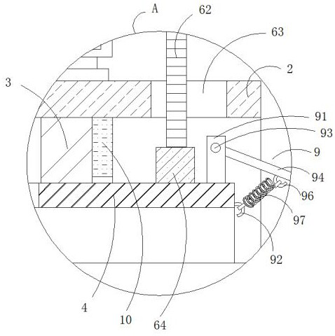
[0032] Such as figure 1 and figure 2 As shown, on the basis of Embodiment 1, preferably, the drive mechanism 6 includes a drive motor 61 fixedly connected to the outer wall of the cooling cylinder 2, the output end of the drive motor 61 is fixedly connected to a gear 62, and the outer wall of the cooling cylinder 2 is opened. There is a connecting through hole 63 matched with the gear 62 , and the outer wall of the side end of the cooling pipe 4 is fixedly sleeved with an external gear ring 64 , and the external gear ring 64 and the gear 62 mesh with each other.

[0033] In actual use, the driving mechanism 6 rotates the cooling pipe 4, and the rotating cooling pipe 4 enables the air discharged from the rectangular air outlet 8 to completely cool the surface of the pipe, improving the cooling effect and reliability of the pipe. Both the starting air pump 5 and the driving motor 61 are electrically connected to the external power supply through the control switch. This electr...

Embodiment 3

[0035] On the basis of embodiment 1 or embodiment 2, such as figure 1 and figure 2As shown, preferably, the lubricating oil cleaning mechanism 9 includes a U-shaped block 91 fixedly connected to the outer wall of the side end of the cooling pipe 4, a first hook 92 fixedly arranged on the end surface of the same side of the cooling pipe 4, and the U-shaped block 91 Both sides of the outer wall are provided with round holes, and each round hole is movably connected with a rotating rod 93, the outer wall of the rotating rod 93 is fixedly connected with an extension rod 94, and the end of the extension rod 94 is connected with a cleaning blade 95.

[0036] In actual use, round holes are provided on the outer walls of both sides of the U-shaped block 91, and each round hole is movably connected with a rotating rod 93, and the outer wall of the rotating rod 93 is fixedly connected with an extension rod 94, and the end of the extension rod 94 is connected to There is a cleaning scr...


PUM


Abstract

The invention relates to the technical field of cold rolling machining, in particular to a discharging air cooling device for a cold pilger mill and an air cooling method. The device comprises a mounting plate, the upper surface of the mounting plate is fixedly connected with a cooling cylinder, the inner wall of the cooling cylinder is fixedly connected with two sealed bearing assemblies, the inner walls of the two sealed bearing assemblies are jointly and fixedly connected with a cooling pipe, the upper surface of the cooling cylinder is fixedly connected with an air pump and a driving mechanism, and the output end of the air pump fixedly communicates with a bent pipe. The bottom end of the bent pipe fixedly communicates with the outer wall of the cooling cylinder, and the outer wall of the side end of the cooling pipe is fixedly connected with a lubricating oil cleaning mechanism. Tubes output from the cold pilger mill are comprehensively and rapidly cooled through the cooling cylinder, the situation that the tubes deform in the transportation process after cold rolling is prevented as much as possible, the quality and the qualification rate of the tubes machined by the cold pilger mill are improved, lubricating oil on the surfaces of the cooled tubes is cleaned through the lubricating oil cleaning mechanism, manual operation is not needed, and the production efficiency is improved. The labor intensity of workers is reduced, and the production efficiency is improved.

Description

technical field [0001] The invention relates to the technical field of cold rolling processing, in particular to a discharge air cooling device and an air cooling method for a cold rolling pipe mill. Background technique [0002] With the rapid development of the national economy and the continuous expansion of new technology fields, the application range of cold-rolled pipes is becoming wider and wider, and the requirements for its variety and quality are getting higher and higher, especially in the development of industries such as aviation, rockets, automobiles, and shipbuilding. , so that the demand for various precision, thin-walled, high-strength cold-rolled pipes is increasing. At present, the production of these pipes is mainly cold-rolled pipe machines. [0003] Although the cold rolling process is carried out at room temperature, the extrusion and extension movements between the roll and the pipe will inevitably cause certain temperature fluctuations. At present, t...

Claims


Application Information

Patent Timeline
Patent Type & Authority Applications(China)
IPC IPC(8): B21B45/02
Inventor 郭琳姚赟曾祥杰曹世奇凡明
Owner CHINA NAT HEAVY MACHINERY RES INSTCO
Learn More