
Pancreaticobiliary duct multiple-plastic-stent implanting device

A technology of a plastic stent and an implantation device, applied in the field of medical devices, can solve the problems of long operation time, low efficiency, affecting stent implantation, etc., and achieve the effect of reducing the difficulty of the operation, improving the implantation efficiency, and facilitating stable fixation.

Inactive Publication Date: 2022-04-15
THE SECOND PEOPLES HOSPITAL OF SHENZHEN
View PDF0 Cites 0 Cited by
  • Summary
  • Abstract
  • Description
  • Claims
  • Application Information

AI Technical Summary

Problems solved by technology

[0003] However, the following problems still exist in the prior art: 1. Due to the difficulty in passing the guide wire in the narrow section of the bile duct and pancreatic duct, before placing multiple plastic stents, it is necessary to indwell a plurality of guide wires, and then place them successively along the guide wires. Inserting a corresponding number of stents, which undoubtedly increases the difficulty of the operation, increases the number of guide wires used, and increases the medical burden; 2. The stability of the existing device for fixing the stent is not high, thereby affecting the implantation of the stent; 3 , The existing device is inefficient in placing multiple plastic stents, which makes the operation time long

Method used


Image

  • Pancreaticobiliary duct multiple-plastic-stent implanting device
  • Pancreaticobiliary duct multiple-plastic-stent implanting device
  • Pancreaticobiliary duct multiple-plastic-stent implanting device

Examples


Embodiment Construction

[0027] In order to make the technical means, creative features, goals and effects achieved by the present invention easy to understand, the present invention will be further described below in conjunction with specific embodiments.

[0028] In the description of the present invention, it should be noted that the terms "upper", "lower", "inner", "outer", "front end", "rear end", "both ends", "one end", "another end" The orientation or positional relationship indicated by etc. is based on the orientation or positional relationship shown in the drawings, and is only for the convenience of describing the present invention and simplifying the description, rather than indicating or implying that the referred device or element must have a specific orientation, use a specific Azimuth configuration and operation, therefore, should not be construed as limiting the invention. In addition, the terms "first" and "second" are used for descriptive purposes only, and should not be understood ...


PUM


Abstract

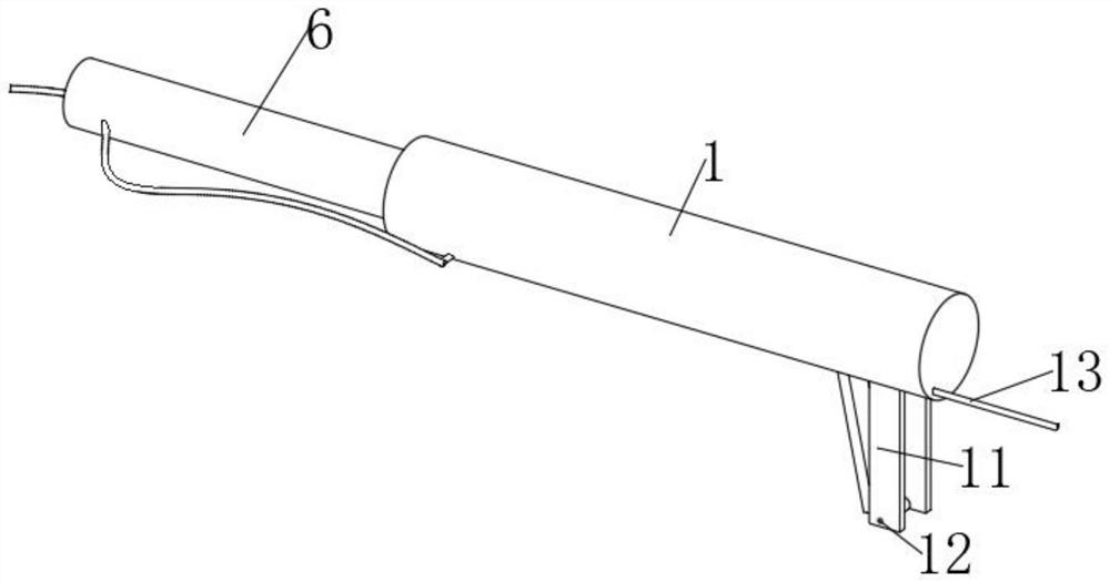
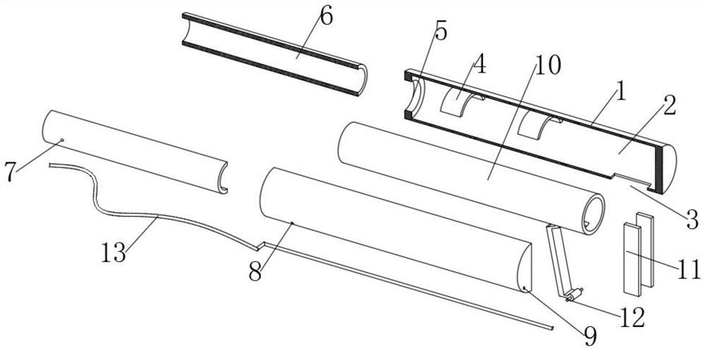
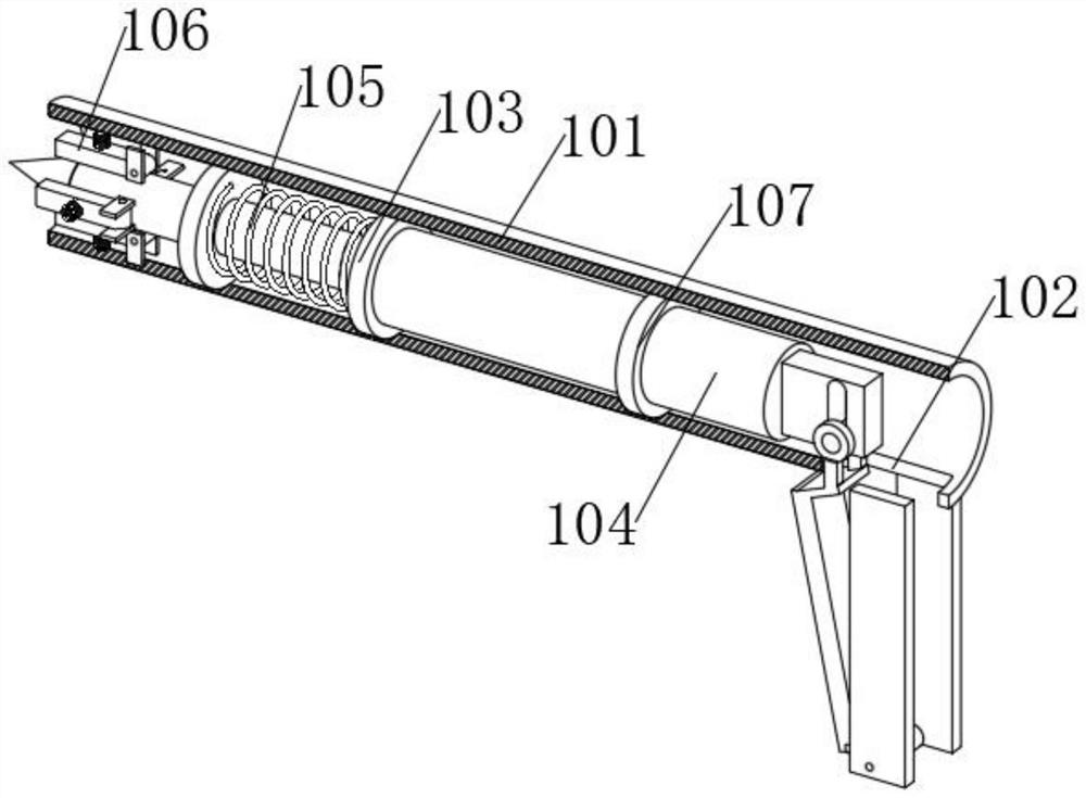
The device comprises a connecting column, a first connecting groove is formed in the connecting column, a fixing groove is formed in the outer surface of the right portion of the lower end of the connecting column, and two positioning blocks are fixedly connected to the left portion of the upper groove wall in the first connecting groove; a boosting device is fixedly connected to the middle of the right end in the first connecting groove, the outer surface of the upper portion of the boosting device is fixedly connected with the two positioning blocks in a penetrating and penetrating mode, a penetrating groove is formed in the middle of the left end of the connecting column, a support pipe is connected into the penetrating groove in a penetrating and penetrating mode, and the right portion of the support pipe penetrates through the right end of the penetrating groove and is connected with the boosting device in a penetrating and penetrating mode; a first guide wire hole is formed in the outer surface of the left portion of the front end of the support tube, and a second guide wire hole is formed in the left portion of the front end of the connecting column. According to the multiple-plastic-stent implanting device for the pancreaticobiliary duct, the multiple plastic stents can be implanted through one guide wire body, so that the operation difficulty is reduced, and the medical cost is reduced.

Description

technical field [0001] The invention relates to the technical field of medical devices, in particular to a device for implanting multiple plastic stents of pancreaticobiliary ducts. Background technique [0002] In the prior art, for benign strictures of the pancreatic and bile ducts, it is necessary to place multiple plastic stents or a single metal stent for drainage and achieve the purpose of expansion and shaping. Due to the small diameter of the plastic stent, in order to achieve the therapeutic effect, it is often necessary to place Many roots. [0003] However, the following problems still exist in the prior art: 1. Due to the difficulty in passing the guide wire through the stenosis of the bile duct and pancreatic duct, before placing multiple plastic stents, it is necessary to indwell a plurality of guide wires, and then place them successively along the guide wires. Inserting a corresponding number of stents, which undoubtedly increases the difficulty of the opera...

Claims


Application Information

Patent Timeline
Patent Type & Authority Applications(China)
IPC IPC(8): A61F2/966A61F2/97
Inventor 刘朝晖孙大勇胡银清李娜杨澜王湘雨
Owner THE SECOND PEOPLES HOSPITAL OF SHENZHEN
Learn More