Far infrared myopia prevention and control glasses

A technology for preventing and controlling glasses and far-infrared. It is applied in glasses/goggles, optics, instruments, etc. It can solve the problems of rough cloth, glasses slipping, lens fogging, etc., and achieve enhanced fit, enhanced comfort, and enhanced stability. sexual effect

Pending Publication Date: 2022-04-12
解嫕颖
View PDF0 Cites 0 Cited by
  • Summary
  • Abstract
  • Description
  • Claims
  • Application Information

AI Technical Summary

Problems solved by technology

[0003] However, when the glasses suddenly go in and out of an environment with a relatively large temperature difference, the lens will be fogged, especially when working outdoors, heat will be generated around the glasses, especially in colder weather, the temperature difference between hot and cold will make the lens foggy. Fog on the surface of the lens will not only affect the vision, especially the blind area caused by the fogging of the lens, if it is not wiped off in time, it will affect the progress of the work. , Not only will it affect the mowing work, but there are also potential safety hazards for personnel, and outdoor sports generally do not carry cleaning cloths for wiping eyes, but when wiping with other cloths such as clothes, there will be unclear wiping, and the cloth It is relatively rough, and there will be wear and tear on the lens, which will seriously affect the service life of the lens, and as the work progresses, people will sweat, so the strong vibration and sweat of the lawn mower will make the nose pads that are in contact with the skin of the bridge of the nose Sliding from the bridge of the nose, causing the glasses to often slip off, causing the problem of unstable wearing, which affects the progress of activities

Method used


Image

  • Far infrared myopia prevention and control glasses
  • Far infrared myopia prevention and control glasses
  • Far infrared myopia prevention and control glasses

Examples


Embodiment Construction

[0026] In order to make the technical means, creative features, goals and effects achieved by the present invention easy to understand, the present invention will be further described below in conjunction with specific embodiments.

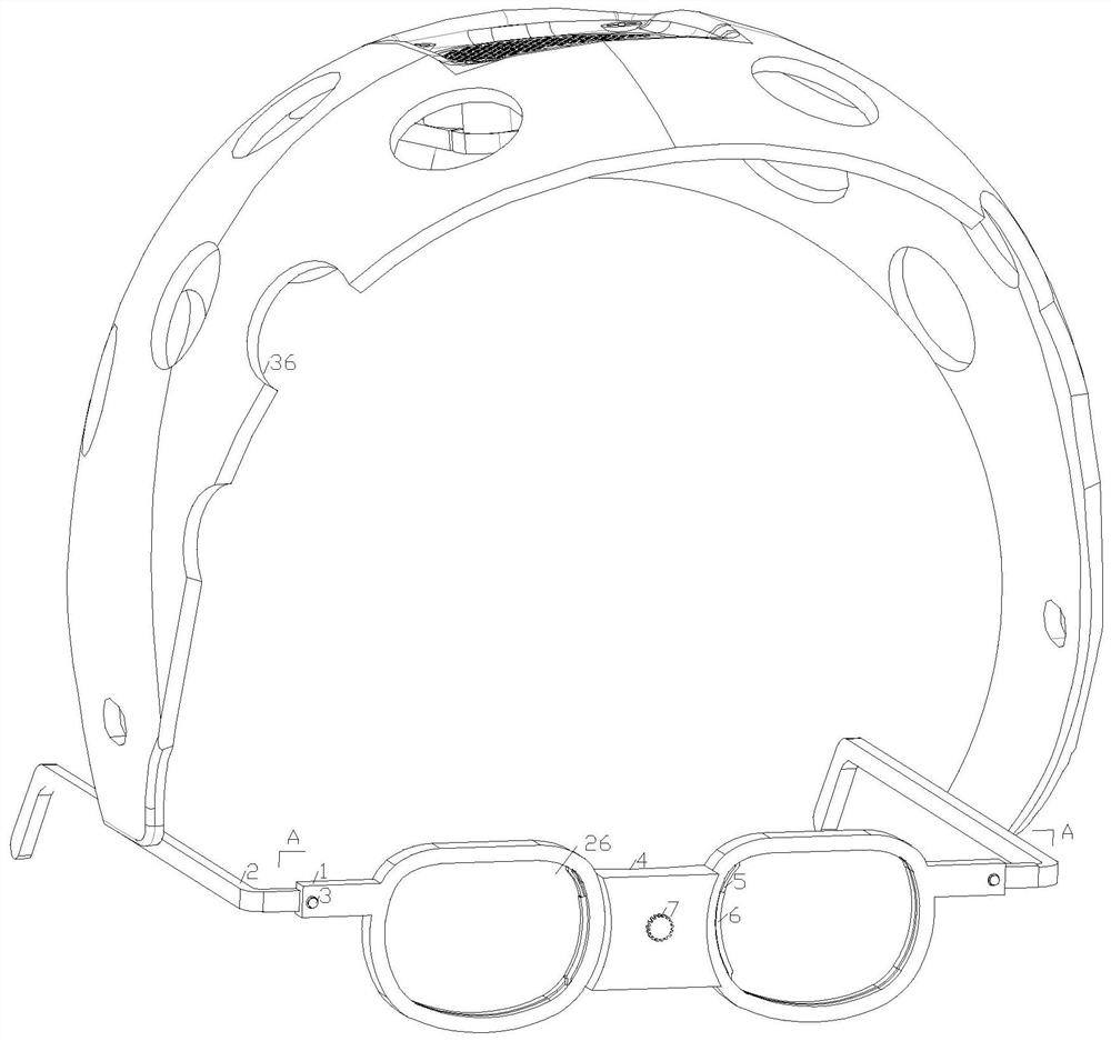
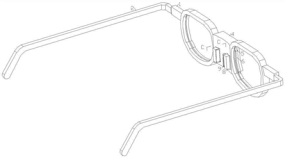
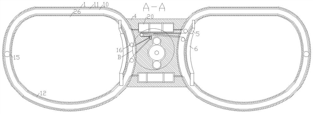
[0027] like Figure 1-Figure 10As shown, a kind of far-infrared myopia prevention and control glasses according to the present invention comprises a picture frame 1 and mirror feet 2, a middle beam block 4 is fixedly installed in the middle of the picture frame 1, and a driving gear 17 is arranged inside the middle beam block 4, and the driving gear 17 The center of the front side is fixedly connected to the driving shaft 21, the front side of the middle beam block 4 is provided with a second button 7, and the other end of the second button 7 is fixedly connected to the driving shaft 21, and the lower side of the driving gear 17 is meshed with the first driven gear 18, The center position of the rear side of the first driven gear 18 is fixedly con...


PUM


Abstract

The invention relates to the field of myopia prevention and control glasses, in particular to far infrared myopia prevention and control glasses which comprise a glasses frame and glasses legs, a middle beam block is fixedly installed in the middle of the glasses frame, a driving gear is arranged in the middle beam block, a driving shaft is fixedly connected to the circle center position of the front side of the driving gear, and a second button is arranged on the front side of the middle beam block. A threaded rod is fixedly connected to the circle center position of the rear side of the first driven gear, a movable sleeve is installed on the outer side of the threaded rod in a matched mode, connecting columns are fixedly arranged on the upper side and the lower side of the movable sleeve correspondingly, and adjusting frames are arranged on the left side and the right side of the movable sleeve correspondingly; the non-end point of the adjusting frame is rotationally installed on the middle beam block, a sliding groove is formed in the end, close to the movable sleeve, of the adjusting frame, the first cleaning brush and the second cleaning brush conduct movable cleaning on the lenses, the movable sleeve rotates left and right through the adjusting frame, left-right distance adjustment of the nose pad is achieved, and demisting and fixing of the glasses are achieved.

Description

technical field [0001] The invention relates to the field of myopia prevention and control glasses, in particular to far-infrared myopia prevention and control glasses. Background technique [0002] Myopia glasses are glasses that are used to correct vision and allow people to see distant objects clearly. The purpose is to maintain a certain adjustment ability of the ciliary muscle of the eyeball. At present, as myopia gradually becomes younger, teenagers generally wear it Myopia glasses, myopia glasses can protect the eyesight of young people to a certain extent. [0003] However, when the glasses suddenly go in and out of an environment with a relatively large temperature difference, the lens will be fogged, especially when working outdoors, heat will be generated around the glasses, especially in colder weather, the temperature difference between hot and cold will make the lens foggy. Fog on the surface of the lens will not only affect the vision, especially the blind ar...

Claims


Application Information

Patent Timeline
Patent Type & Authority Applications(China)
IPC IPC(8): G02C11/08G02C5/12G02C5/04G02C5/06
Inventor 解嫕颖汪铮
Owner 解嫕颖
Why Eureka
Try Eureka